4-19
4-4 Wiring Servo Motor
SIGNALS AND WIRING
- SV Series User’s Manual -
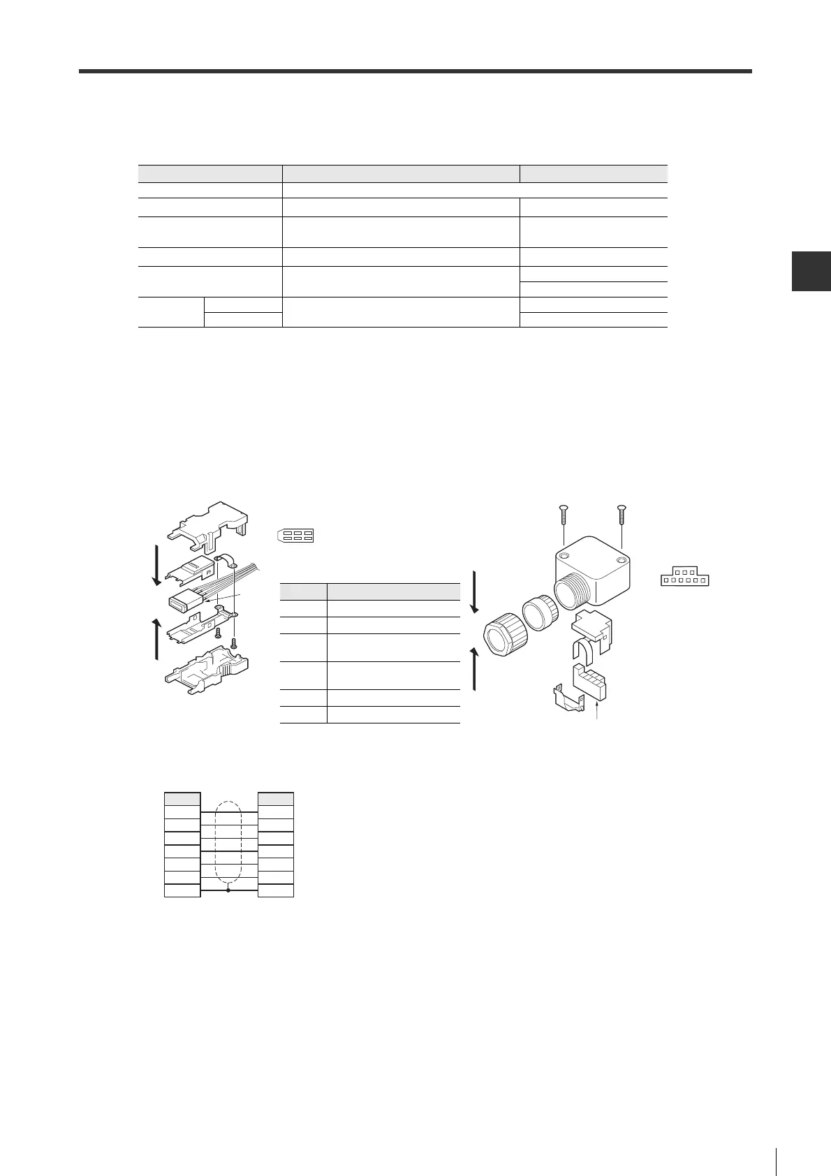
■ Encoder cable(50W to 750W)
● Components and specifications
● How to wire
The connector at servo amplifier side is soldered when wiring, while the connector at servo amplifier side is crimped
with crimping tool.
Servo amplifier side (Fig. (1)) Servo motor side (Fig. (2))
● Wiring diagram
Encoder connector Servo amplifier side (Fig. (1)) Servo motor side (Fig. (2))
Vendor Molex Ltd.
Model 55100-0670(welding) 54346-0070(crimping)
*1
*1 For 54346-0070, the contacts are not included in the packaging; if necessary, be sure to use the 56161-8081 made
by Japan molex Co.,Ltd. (sold by reel).
Supported wire size
AWG #16 MAX(Pin No.1,2,5,6)
AWG #22 MAX(Pin No.3,4)
AWG#26 to #22
Supported wire O.D. φ 6.2 to 7.2mm φ 6.5 to 7.7mm
User's Manual PS-54280
AS-54992
CS-56161
Crimping tool
Hand tool
unnecessary for welding
57175-5000
Applicator 57175-3000
soldering
surface
1
2
35
46
Connector soldering view
7
4
89
56
Connector bottom view
321
bottom
Pin No.
Signal name
1
5V
2
GND
3
BAT+ (For battery
connection)
4
BAT- (For battery
connection)
5
PS+(Signal)
6
PS-(Signal)
Servo amplifier side Servo motor side
Pin No.
6
5
4
3
2
1
Shell
Pin No.
5
4
8
9
3
6
Shell
Shielded wire
 Loading...