4-20
SIGNALS AND WIRING
4-4 Wiring Servo Motor
- SV Series User’s Manual -
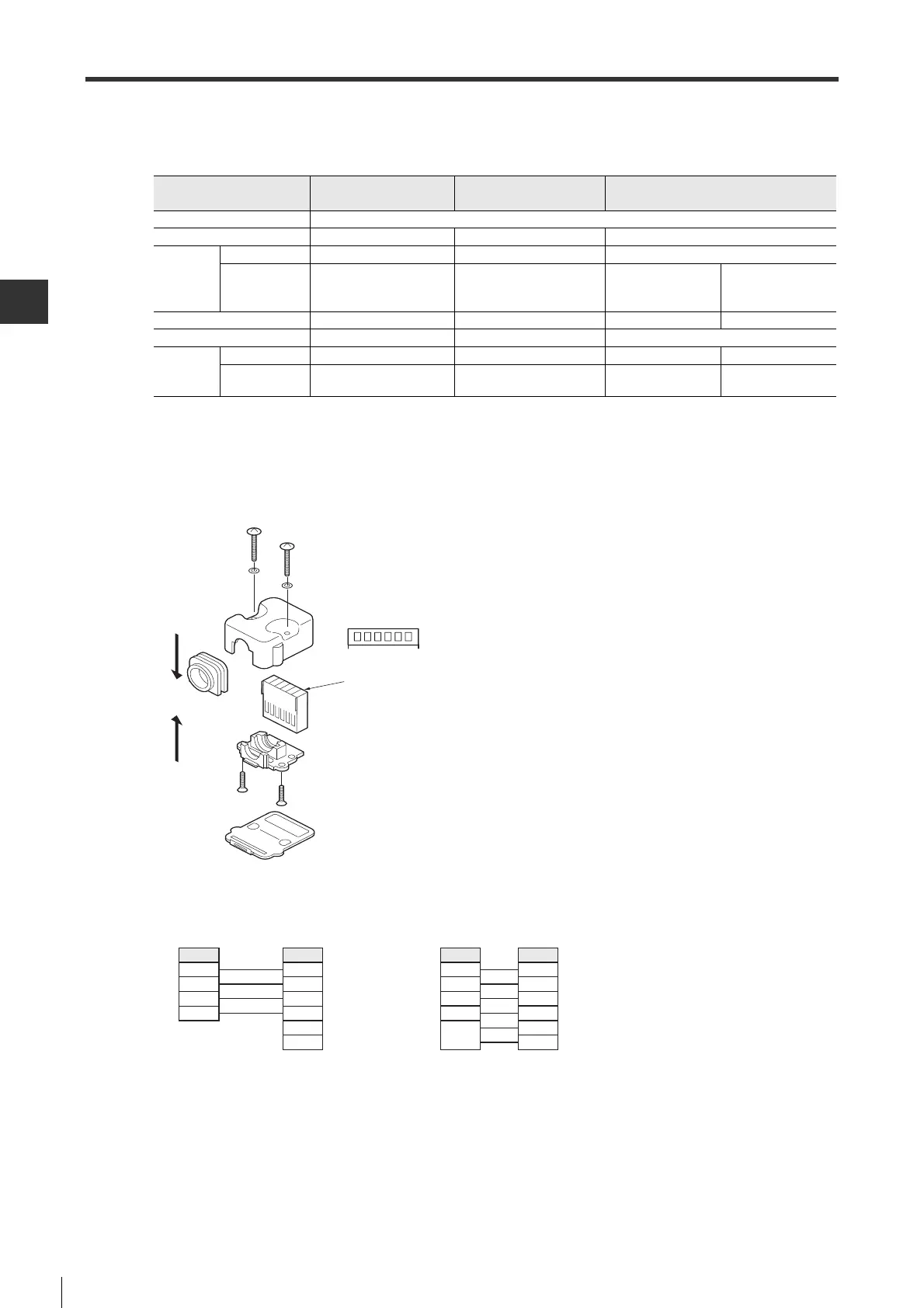
■ Motor power cable(50W to 750W)
● Components and specifications
● How to wire
The wires at servo amplifier side adopts barbed wires, while the connector at servo amplifier side is crimped with
crimping tool.
Servo motor side
● Wiring diagram
Standard motor Electromagnetic brake motor
Motor power connector
(Fig. 3)
For 50W/100W For 200W/400W For 750W
Vendor J.S.T. Mfg Co., Ltd
User's Manual JFA Connector J-1700 JFA Connector J-2700 JFA Connector J-3700
Used
components
Socket J17-06FMH-7KL-1-CF J27-06FMH-7KL-1-CF J37-06FMH-8KL-1L-CF
Contact SJ1F-01GF-P0.8 SJ2F-01GF-P1.0
SJ3F-41GF-P1.8
(For power terminal)
SJ3F-01GF-P1.8
(For electromagnetic
brake terminal)
Supported wire size AWG#24 to #20 AWG#24 to #20 AWG#20 to #16 AWG#24 to #20
Supported wire O.D.
φ 7±0.3mm φ 7±0.3mm φ 8±0.3mm
Crimping
tool
Hand tool YRS-8841 YRS-8861 YRF-880 YRF-881
Applicator
APLMK
SJ1F/M-01-08
APLMK
SJ2F/M-01-08
APLMK
SF3F/M-41-20
APLMK
SF3F/M-01-20
321
Connector crimping
surface view
456
Crimping surface
Servo amplifier side
Servo motor side
Signal name
FG
W phase
V phase
U phase
Pin No.
1
2
3
4
5
6
Servo amplifier side Servo motor side
Signal name
FG
W phase
V phase
U phase
Pin No.
1
2
3
4
5
6
Electromag-
netic brake
Connector view
seen from the outer
side of SV
 Loading...