4-31
4-5 Wiring I/O Signals
SIGNALS AND WIRING
- SV Series User’s Manual -
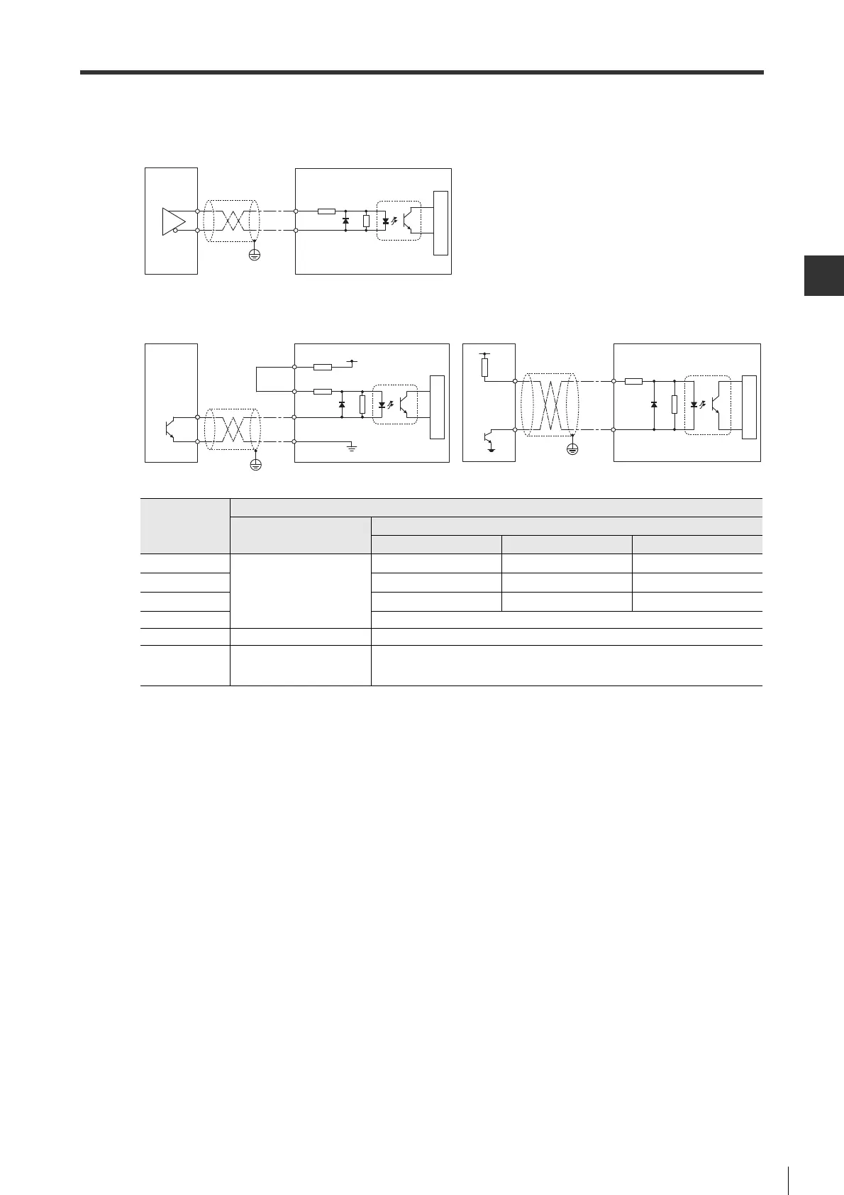
■ Pulse input (DI-P)
* Recommended input current: 7 to 15mA
Item
Specification
Differential line driver
Open collector (R1 resistance)
*
2.2k 1k 180
Max. input voltage
AM26C31 or similar
DC24V+5% DC12V+5% DC5V+5%
Rated input voltage
DC24V DC12V DC5V
Min. ON voltage 18.3V 9.9V 4.2V
Max. OFF current
0.1mA
Common mode
Independent (non-isolation)
Common
Response
frequency
1-phase : 4MHz
2-phase : 4MHz
200kHz
Higher-level equipment
AM26C31
or similar
PP+, NP+
PP
-
, NP
-
150Ω
Opto-isolation
Internal circuit
4.7kΩ
High-level equipment
150Ω
Opto-isolation
Internal circuit
PP+, NP+
PP
-
, NP
-
1kΩ
PL1, PL2
SG
4.7kΩ
+12V
Higher-level equipment
150Ω
Opto-isolation
Internal circuit
PP+, NP+
4.7kΩ
Vcc
PP
-
, NP
-
R1
Line driver input
Open collector input
(When built-in power supply of servo amplifier is used)
(When external power supply is used)
 Loading...