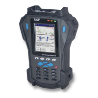
Frequency Response Function Module
How to Set Up an FRF Measurement
The Variable sensor option allows you to configure settings for a
sensor that is not on the sensor list.
Sensor Units – (Not editable if a preconfigured sensor is selected in the Sensor field.)
When the Variable sensor is selected, select the measurement units to use for the type
of sensor being used. Options include g, in/s, and mil.
Sensitivity – (Not editable if a preconfigured sensor is selected in the Sensor field.)
When the Variable sensor is selected, use the alphanumeric keypad to enter transducer
sensitivity in millivolts (mV) per Engineering Unit (EU).
ICP Power – (On or Off), (Not editable if a preconfigured sensor is selected in the
Sensor field.) When the Variable sensor is selected, select to turn ICP power Off or On
for the sensor.
Response Range – Sets response sensor input range manually to selected fixed range,
or to be set automatically.
If Hammer Range or Response Range is set to Automatic, the
user is prompted to make three trial hits to establish the range to
use.
Hammer Units – Set to N for metric, or lbf for English units.
This setting does not restrict the Meas Units options; e.g., if
Hammer Units is lbf, mobility can still be measured in mm/sec/N,
if desired.
H.Sens – Enter the sensitivity of the hammer in mV/N or mV/lbf.
H. ICP Power - (On or Off), Select to turn ICP power Off or On for the hammer.
Hammer Range – Sets hammer input range manually to selected fixed range, or to be
set automatically.
Measurement – Sets FRF display type. Available measurement display types are
Mobility, Apparent Mass, Accelerance, Impedance, Stiffness and Compliance.
Meas Units – Measurement units change to correspond with the measurement display
type that has been chosen, but can be set to English or metric units as per the list.
Y-axis – Sets Y axis to linear, logarithmic or decibel scale.
Freq Range – Sets the frequency range for the test. The Acquisition time information
box will change accordingly.
Num of Lines – Sets the number of lines of resolution for the FFT. The Acquisition
time information box will change accordingly.
When set to Automatic, the FRF module automatically chooses
the number of lines after three trial hits. This uses a Uniform
window if possible and automatically increases the lines of
resolution to accommodate the decay time. If this cannot be
achieved, then Force / Exponential will automatically be selected.
This feature is optimized to work for frequency ranges between
200Hz and 4kHz. If Automatic is selected at a frequency range
outside this band, the algorithm attempts to auto select, but may
not achieve such good results.
8 - 6 SKF Microlog - GX Series
User Manual

 Loading...