ID 442426.04 109WE KEEP THINGS MOVING
Connection
7
Manual SD6
7.4.2 X101
X101 specification
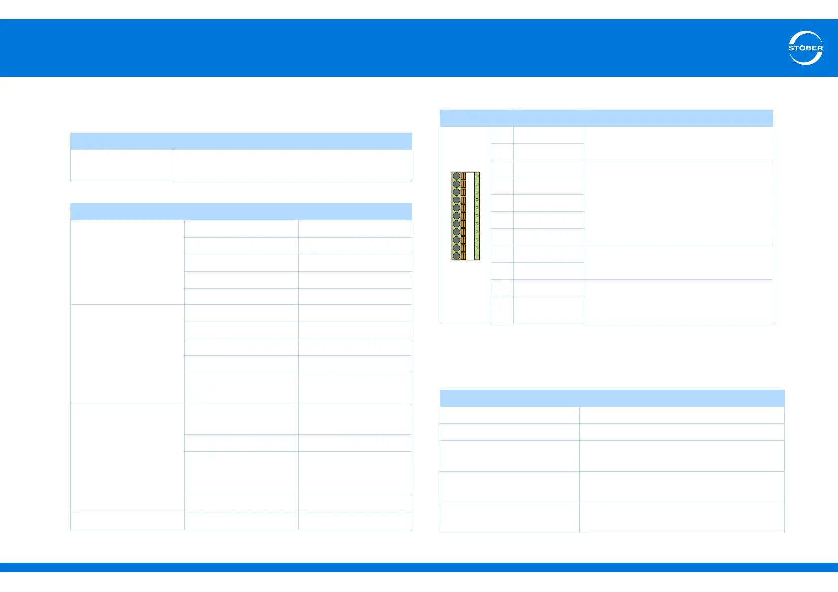
Terminal description X101 for binary signals
General specification
Maximum cable
length
30 m, shielded
Electrical data
Binary inputs
BE1 to BE3
Low level 0–8 V
High level 12–30 V
Input voltage Max. 30 V
Input current Max. 16 mA
Input frequency Max. 10 kHz
Binary inputs
BE4 and BE5
Low level 0–8 V
High level 12–30 V
Input voltage Max. 30 V
Input current Max. 16 mA
Input frequency XI6: max. 100 kHz
IO6, RI6: max. 250 kHz
Binary outputs
BA1 and BA2
Maximum output current XI6: 50 mA
IO6, RI6: 100 mA
Typical voltage drop < 2 V
Refresh rate Cycle time of the
application (at least 1
ms)
Output frequency Max. 250 kHz
24 vdc power supply Input voltage 18–28.8 V
Pin Designation Function
9DGND
Reference ground
10 DGND
11 BE1
Binary input
12 BE2
13 BE3
14 BE4
15 BE5
16 BA1
Binary output
17 BA2
18 24 V-In 24-V supply for all binary outputs and
binary inputs BE6 to BE13.
Recommended fuse: max. 1 AT
a)
a) Use a 1 A fuse (delayed-action) upstream from relay 1 for fuse protection. Make certain for
UL-compliant operation that the fuse has been approved for the requirements of UL 248.
19 24 V-In
Maximum conductor cross-section
Connection type Maximum conductor cross-section [mm
2
]
Rigid 1.5
Flexible 1.5
Flexible with cable end,
without plastic sleeve
1.5
Flexible with cable end, with
plastic sleeve
0.5
2 leads with the same cross-
section with double cable end
—
9
10
11
12 13 14 15 16 17 18 19