ID 442426.04 196WE KEEP THINGS MOVING
Drive controller
9
Manual SD6
9.8 Input and output signals
9.8.1 Binary inputs
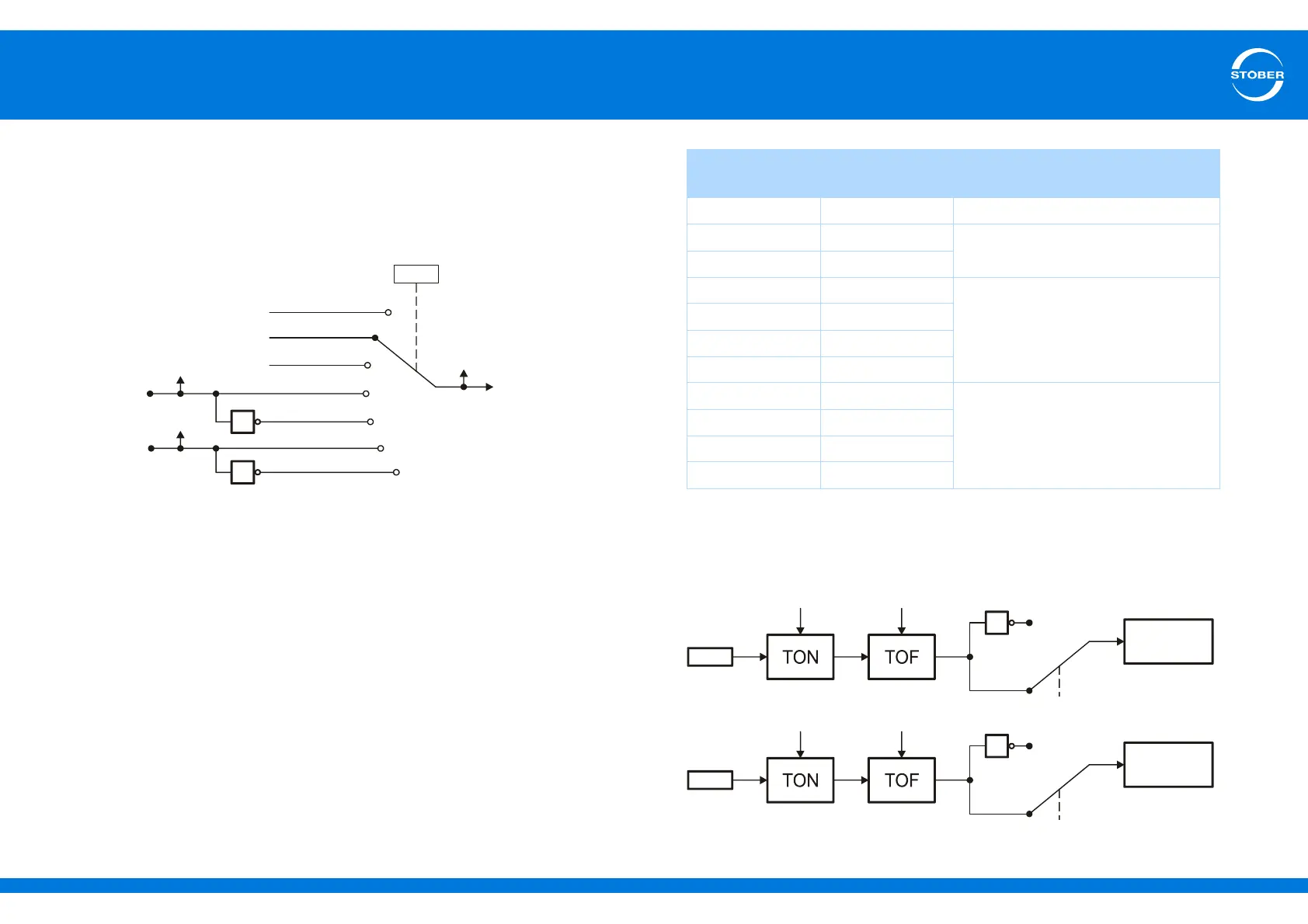
The section below explains with the quick stop as an example how to link
binary input signals with the application:
The signal can be made available on various binary inputs or via fieldbus. The
user makes the selection with a selector, in this case A62. There is also a
display parameter that shows the signal state (in this case A302).
9.8.2 Binary outputs
To be able to poll application status signals, the signals must be allocated to an
output. To do this enter the signal you would like to generate on a binary output
in the corresponding source parameter. The table below shows the assignment
of source parameters to binary outputs as well as the interface on which the
binary output is present.
The signals for relay 1 and binary outputs 3 to 10 are unchanged and are
directed to the interface. For binary output 1 and 2 you can parameterize a
switch-on and switch-off delay as well as an inversion according to the graphic
below:
A62
BE1
2:Parameter
1
1
4:BE1-inverted
5:BE2
6:BE2-inverted
1:High
0:Low
E19.1
E19.2
3:BE1
.
.
.
BE2
A302
Application
Output Source
parameter
interface
Relay 1 F75 X1 (basic device)
BA1 F61 X101 (with XI6 only)
BA2 F62
BA3 F63 X103A (with XI6 only)
BA4 F64
BA5 F65
BA6 F66
BA7 F67 X103B (with XI6 only)
BA8 F68
BA9 F69
BA10 F70