ID 442426.04 129WE KEEP THINGS MOVING
Connection
7
Manual SD6
Terminal description X305 for connecting HIWIN-TTL
Terminal description X306 for connecting HIWIN-TTL
7.7 Cables
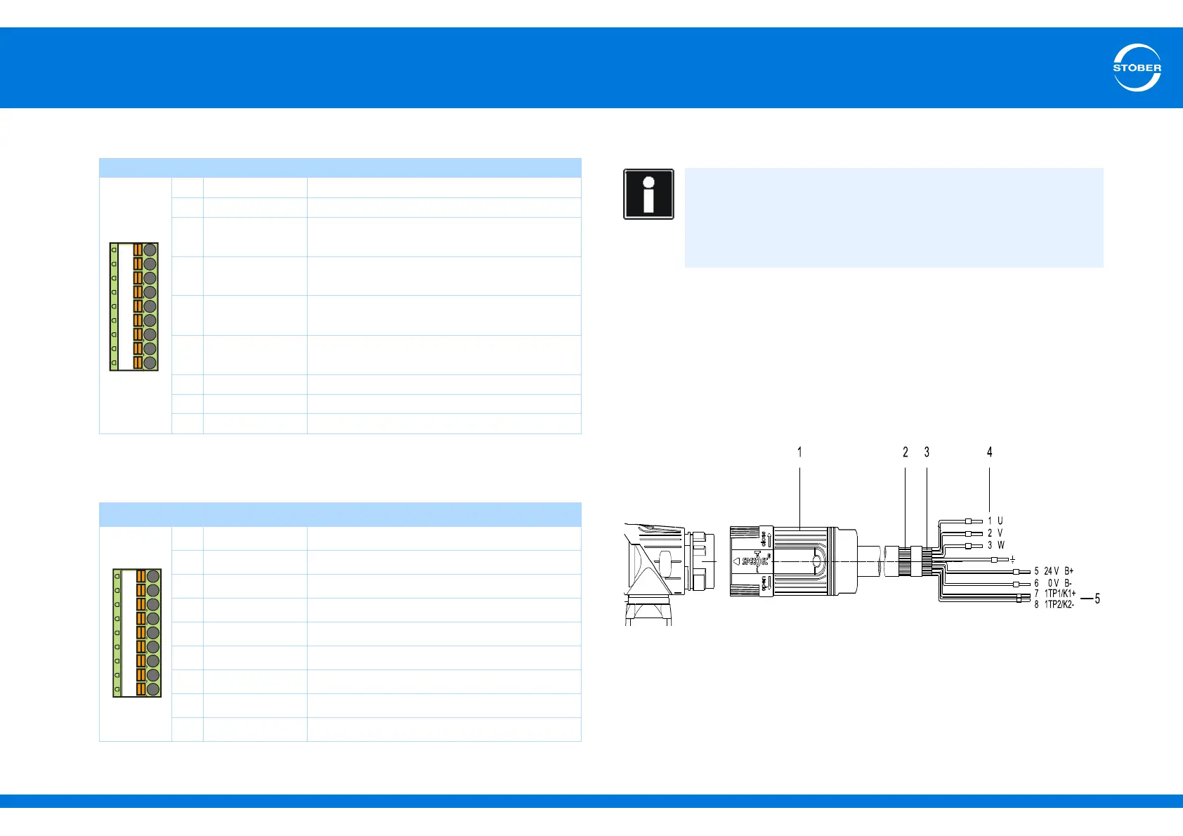
7.7.1 Power cable
Please observe the motor connection diagram that is delivered with every
synchronous servo motor.
Power cables are available depending on the plug size in the following designs:
• SpringTec quick lock for con.15
• SpeedTec quick lock for con.23 and con.40
• Screw technology for con.58
1 Plug connector (quick/screw lock)
2 Cable shield
3 Junction of all shields
4 Wire no.
5 Motor, brake temperature sensor
Pin
a)
a) Connection via loose cable ends: Pin assignment corresponds to terminal X304, pins 1–9.
Designation Function, data
1HALL A
2U
2
Encoder supply
3 N- Inverse, differential input for
N channel
4 B- Inverse, differential input for
B channel
5 A- Inverse, differential input for
A channel
6 Sense Sensor line for the supply voltage to adjust
the encoder supply
7—
8—
9HALL B
Pin
a)
a) Connection via loose cable ends: Pin assignment corresponds to terminal X304, pins 10-15.
Designation Function, data
1 GND Reference for encoder supply
2 N+ Differential input for N channel
3 B+ Differential input for B channel
4 A+ Differential input for A channel
5HALL C
6—
7—
8—
9—
Information
To ensure proper functionality of the drive we recommend using
cables from STOBER that are coordinated with the system. In case
of use of unsuitable connection cables, we reserve the right to reject
claims under the warranty.