ID 442426.04 90WE KEEP THINGS MOVING
Connection
7
Manual SD6
7.2.2.3 Housing ground
Note the following information on the connection of the protective earth to
ground the housing correctly:
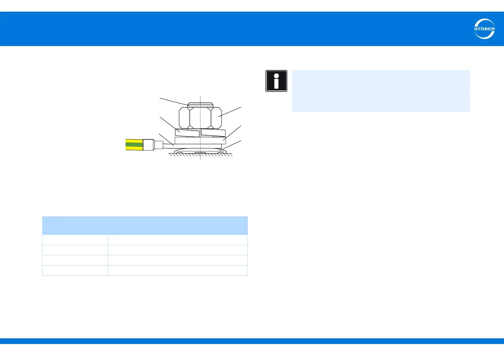
• Note the assembly sequence:
• 1 M6 earth bolt
• 2 Contact disk
• 3 Cable socket
•4 Washer
• 5 Return spring
(optional)
•6 Nut
Contact disk, washer,
return spring and nuts are supplied with the drive controller.
• Tightening torque: 4 Nm
• Stray currents > 10 mA can arise in normal operation. To fulfill DIN EN
61800-5-1 and EN 60204-1, connect the earth bolts with a copper
conductor according to the following table:
7.2.3 EMC connection
• Lay the power line, motor cable and signal lines separately from each other,
e.g. in separate cable channels.
• Only use shielded, low-capacitance cables as motor cables.
• If the brake line is carried in the motor cable, it must be separately shielded.
• Connect the shield of the motor cable with large contact areas and in the
immediate vicinity of the drive controller. Use the EM6 EMC shroud to do
this.
• Shield the cable for connection to a braking resistor if it exceeds a length
of 30 cm. In this case, connect the shield with large contact areas and in
the immediate vicinity of the drive controller.
• For motors with terminal boxes, connect the shield to the terminal box with
large contact areas. For example, use EMC cable screw connections.
• Connect the shield of the control lines on one side with the reference
ground of the source, e.g. the PLC or CNC.
Cross-section A
Feeder
Minimum cross-section A
min
Earth conductor at earth bolts
A ≤ 2.5 mm
2
2.5 mm
2
2.5 < A ≤ 16 mm
2
A
16 – 35 mm
2
≥16 mm
2
> 35 mm
2
A/2
Information
This section provides general information on EMC-compliant
installation. This involves recommendations. Depending on the
application, ambient conditions as well as the legal requirements,
measures beyond these recommendations may be required.