ID 442426.04 20WE KEEP THINGS MOVING
Components of the drive system
3
Manual SD6
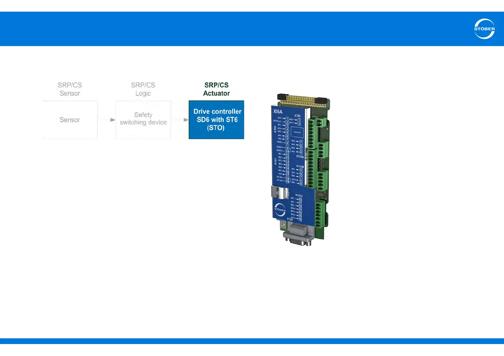
In the safety block diagram (Fig. 3-2 Safety block diagram) the SD6 drive
controller with the ST6 safety card corresponds to the actuator and forms the
basis for a restart inhibit:
Fig. 3-2Safety block diagram
Detailed information about using the safety technology and the ST6 safety card
can be found in the corresponding manual (see section 1.2 Further
documentation).
3.4.2 Terminal modules
Terminal module XI6
ID no. 138421
Terminal module for connecting analog and
binary signals as well as encoders.
Supported inputs and outputs:
• 13 binary inputs (24 V)
• 10 binary outputs (24 V)
• 3 analog inputs (± 10 V, 1 x 0 – 20 mA, 16
bits)
• 2 analog outputs (± 10 V, 12 bits)
Supported encoders / interfaces:
• SSI encoder (simulation and evaluation)
• TTL incremental encoder, differential
(simulation and evaluation)
• HTL incremental encoder, single-ended
(simulation and evaluation)
• TTL pulse train, differential (simulation and
evaluation)
• HTL pulse train, single-ended (simulation
and evaluation)