ID 442426.04 21WE KEEP THINGS MOVING
Components of the drive system
3
Manual SD6
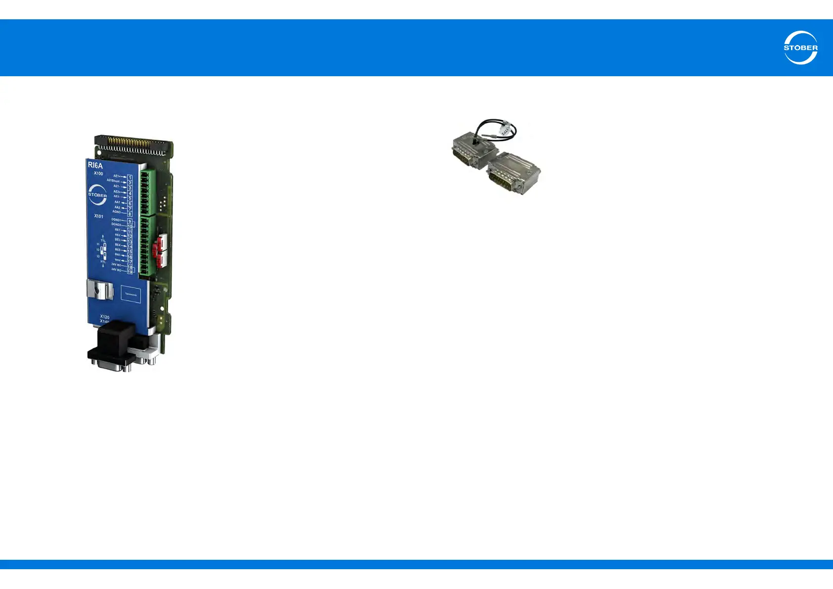
Terminal module RI6
ID no. 138422
Terminal module for connecting analog and
binary signals as well as encoders.
Supported inputs and outputs:
• 5 binary inputs (24 V)
• 2 binary outputs (24 V)
• 2 analog inputs (± 10 V, 1 x 0 – 20 mA, 16
bits)
• 2 analog outputs (± 10 V, ± 20 mA, 12 bits)
Supported encoders / interfaces:
• Resolver (evaluation)
• Encoder EnDat 2.1 sin/cos (evaluation)
• Encoder EnDat 2.1/2.2 digital (evaluation)
• Sin/cos encoder (evaluation)
• SSI encoder (simulation and evaluation)
• TTL incremental encoder, differential
(simulation and evaluation)
• TTL incremental encoder, single-ended
(evaluation)
• HTL incremental encoder, single-ended
(simulation and evaluation)
• TTL pulse train, differential (simulation and
evaluation)
• TTL pulse train, single-ended (evaluation)
• HTL pulse train, single-ended (simulation
and evaluation)
Interface adapter AP6
Encoder cables that were connected to a
POSIDYN SDS 4000 can be connected via the
AP6 interface adapter to the X140 encoder
interface of the RI6 terminal module.
The following versions are available:
AP6A00
ID no. 56498
Adapter X140 resolver, 9/15-pin.
AP6A01
ID no. 56522
Adapter X140 resolver, 9/15-pin with motor
temperature sensor - lead through.
AP6A02
ID no. 56523
Adapter X140 EnDat 2.1 sin/cos, 15/15-pin with
motor temperature sensor - lead through.