ID 442426.04 126WE KEEP THINGS MOVING
Connection
7
Manual SD6
7.6.4 X301
Terminal description X301
7.6.5 X302
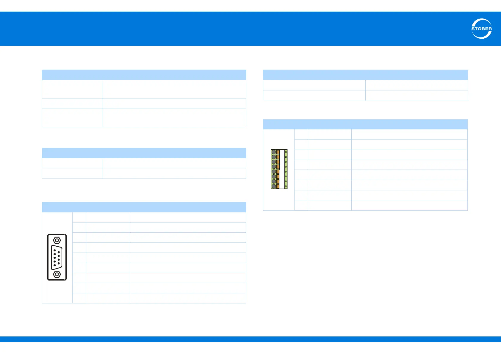
Terminal description X302
General specification
U
2
a)
a) The drive controller forwards the output voltage to the encoder.
15 V
I
2max
250 mA
Maximum cable
length
50 m
Specification for incremental signals
f
max
≤ 1 MHz
Signal level TTL
Pin
a)
a) 1:1 connection to LA6: pin assignment corresponds to terminal X120 (on terminal module XI6
or RI6).
Designation Function
Connector
1 GND-HALL Reference potential for pin 2 to pin 7
2 HALL C+ Differential input/output for HALL C
3 HALL C- Inverse, differential input/output for HALL C
4 HALL A- Inverse, differential input/output for HALL A
5 HALL A+ Differential input/output for HALL A
6 HALL B+ Differential input/output for HALL B
7 HALL B- Inverse, differential input/output for HALL B
8U
2
b)
b) LA6 passes on the encoder supply to the drive controller.
Encoder supply
9 GND Reference for pin 8
General specification
I
2max
50 mA
Typical voltage drop < 2 V
Pin
a)
a) Connection to SD6, terminal X101 (on terminal module XI6, RI6 or IO6).
Designation Function
1 HALL A 24-V power supply output
2 HALL B 24-V power supply output
3 HALL C 24-V power supply output
4 – Reserve
5 – Reserve
6 HW-End1 Hardware limit switch 1
7 HW-End2 Hardware limit switch 2
8 DGND Reference ground