ID 442426.04 111WE KEEP THINGS MOVING
Connection
7
Manual SD6
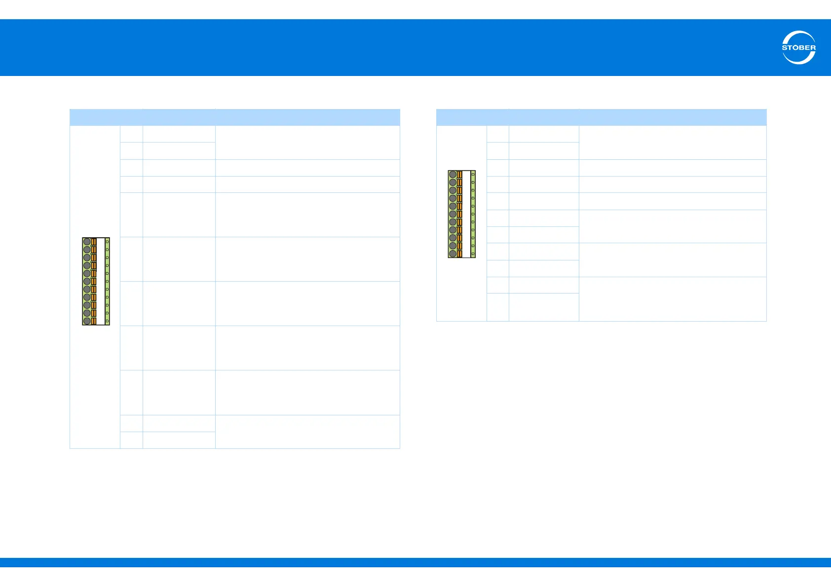
Terminal description X101 – Incremental encoder and pulse train Terminal description X101 for Hall sensor
Pin Designation Function
9DGND
Reference ground, bridged internally
10 DGND
11 BE1 —
12 BE2 —
13 BE3 Evaluation
Incremental encoder: N
Pulse train: –
14 BE4 Evaluation
Incremental encoder: A
Pulse train: frequency–
15 BE5 Evaluation
Incremental encoder: B
Pulse train: direction
16 BA1 Simulation
Incremental encoder: A
Pulse train: frequency–
17 BA2 Simulation
Incremental encoder: B
Pulse train: direction
18 24 V-In
24 vdc power supply, bridged internally
19 24 V-In
9
10
11
12 13 14 15 16 17 18 19
Pin
a)
a) Connection to LA6, terminal X302.
Designation Function
9DGND
Reference ground
10 DGND
11 BE1 HALL A
12 BE2 HALL B
13 BE3 HALL C
14 BE4
Binary input
15 BE5
16 BA1
Binary output
17 BA2
18 24 V-In 24 vdc power supply for all binary outputs
and binary inputs BE6 to BE13.
Recommended fuse: max. 1 AT
b)
b) Use a 1 A fuse (delayed-action) upstream from relay 1 for fuse protection. Make certain for
UL-compliant operation that the fuse has been approved for the requirements of UL 248.
19 24 V-In
9
10
11
12 13 14 15 16 17 18 19