ID 442426.04 101WE KEEP THINGS MOVING
Connection
7
Manual SD6
7.3.7 X5, X6: Motor holding brake
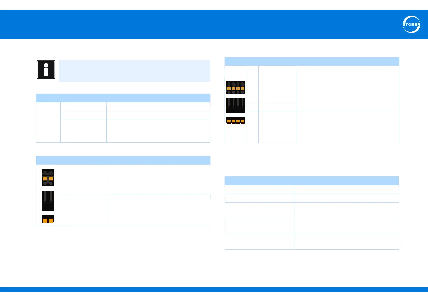
Terminal description X5
Terminal description X6
Information
Note that motor holding brakes from other manufacturers may only
be connected after consultation with STOBER.
Electrical data
Brake
U
1
24–30 V
I
1max
3.0 A
Maximum
switching
frequency
1 Hz
Pin Designation Function
5 1BD1 Control brake
6 1BD2 Reference potential
Pin Designation Function
1 Acknowledge-
ment
Acknowledgement input of an optional
switching amplifier for brake diagnostics –
provided the holding brake is connected to
the SD6 indirectly (for example via a coupling
contactor)
2 GND Reference potential for acknowledgement
+ + 24 V Power supply voltage for the brake
Recommended fuse: max. 6 AT
a)
a) Use of a 4 A fuse (slow-blow) is mandatory for a UL-compliant application. The fuse must be
approved according to UL 248.
- GND Reference potential for power supply voltage
of the brake
Maximum conductor cross-section
Connection type Maximum conductor cross-section [mm
2
]
Rigid 2,5
Flexible 2,5
Flexible with cable end,
without plastic sleeve
2,5
Flexible with cable end, with
plastic sleeve
2,5
2 leads with the same cross-
section with double cable end
—