ID 442426.04 177WE KEEP THINGS MOVING
Drive controller
9
Manual SD6
9.2.7 Operational state
Auxiliary values for displaying the ready for operation message.
Can be used for example for relay 1 F75 or for the status word A66/A67 defined
by the user.
9.2.8 Display
Sources for the bits of user status word A67.
• Element 0: Source for A67 bit 0
• Element 1: Source for A67 bit 1
• Element 2: Source for A67 bit 2
• Element 3: Source for A67 bit 3
• Element 4: Source for A67 bit 4
• Element 5: Source for A67 bit 5
• Element 6: Source for A67 bit 6
• Element 7: Source for A67 bit 7
• Element 8: Source for A67 bit 8
• Element 9: Source for A67 bit 9
• Element 10: Source for A67 bit 10
• Element 11: Source for A67 bit 11
• Element 12: Source for A67 bit 12
• Element 13: Source for A67 bit 13
• Element 14: Source for A67 bit 14
• Element 15: Source for A67 bit 15
The user status word allows the user to define his own status word.
You can adjust the sources for each bit in A66.
A67 is updated in real time (A150) in the drive controller.
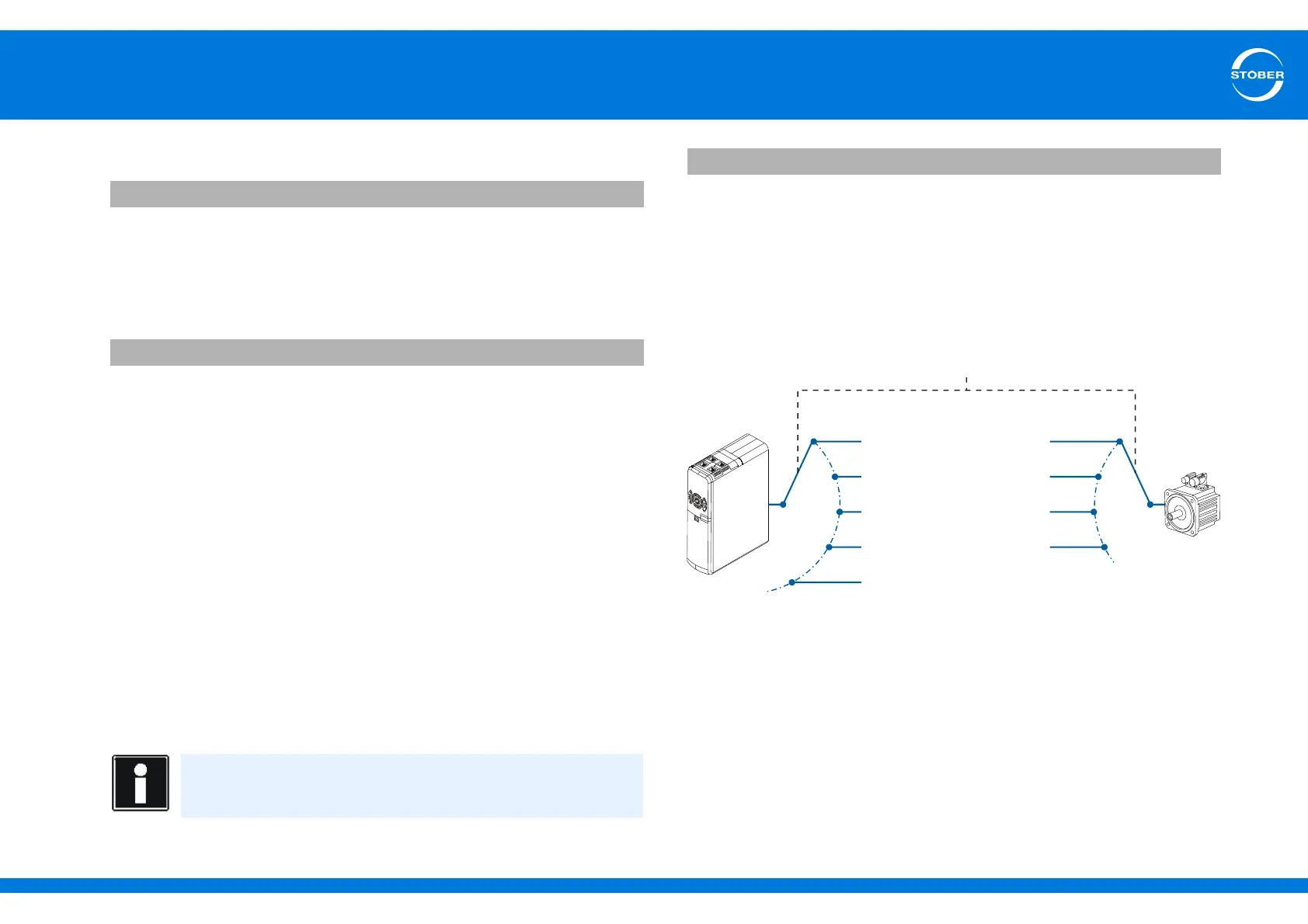
9.3 Axis management
A drive controller can administer up to four axes, of which no more than one is
active. You can use the axes like parameter sets for a connected motor.
E79 operational state version 0
A66 user statusword sources version 0
Information
The bit addressing can be used to specify the sources.
A67 user statusword version 0
Axis 1 = parameter set 1
Axis management
Axis 2 = parameter set 2
Axis 3 = parameter set 3
Axis 4 = parameter set 4
no axis active