ID 442426.04 96WE KEEP THINGS MOVING
Connection
7
Manual SD6
7.3.2 X10: 230 V/400 V power
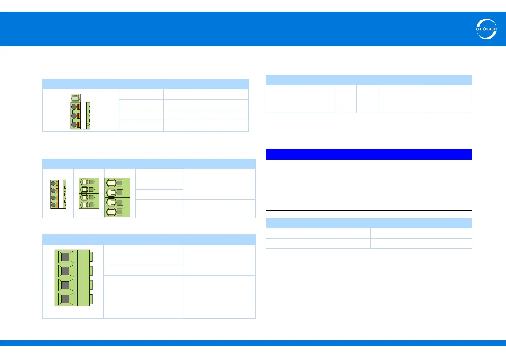
Terminal description – single-phase power connection size 0
Terminal description – three-phase power supply connection size 0, size
1 and size 2
Terminal description – three-phase power supply connection size 3
Maximum conductor cross-section of power supply connection
terminals
7.3.3 X11: 24 V power
Connection of 24 V to X11 is required for powering the control part.
NOTICE
Device damage due to overload!
If the 24-V supply is looped to multiple devices via terminal X11, the device may
be damaged by a current that is too high.
Make certain that the current via terminal X11 does not exceed 15 A (UL:
10 A).
Pin Designation Function
— Plastic dummy plug
L1 Input voltage
N Neutral conductor
PE Protective ground
Pin Designation Function
Size 0 Size 1 Size 2 L1
Input voltageL2
L3
PE Protective ground
Pin Designation Function
L1
Input voltageL2
L3
PE Protective ground
Size 0 1 2 3
Max. cross-section for
conductor with ferrule
[mm
2
]
2.5 4
6
(10 for rigid
conductors)
25
(35 for rigid
conductors)
Control board
U
1
20.4 – 28.8 V
I
1max
a)
a) Depending on the accessories
1.5 A