ID 442426.04 36WE KEEP THINGS MOVING
Technical data
4
Manual SD6
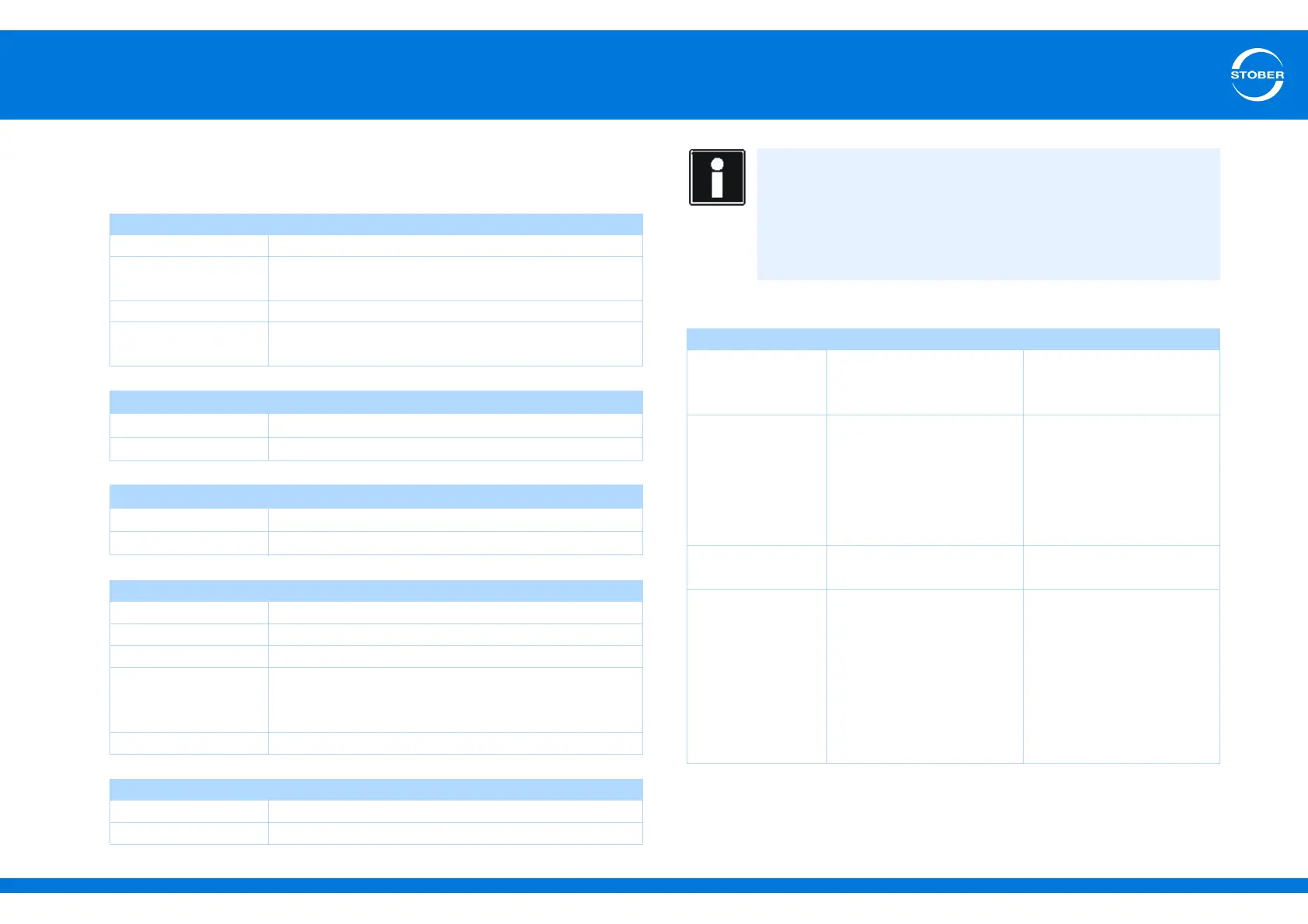
4.5.1 Evaluatable encoders
4.5.1.1 Connection X4
Encoder supply
General specification
U
2
5-15 V (see encoder supply)
I
2max
X4: 250 mA
Sum X4, X120, X140: 500 mA
I
2min
13 mA
Maximum cable
length
100 m
Specification for EnDat 2.1
Encoder type Single and Multiturn, not suitable for linear encoders
Switching frequency 2 MHz
Specification for EnDat 2.2
Encoder type Single-turn and multiturn
Switching frequency 4 MHz
SSI specification
Switching frequency 250 kHz
Sampling rate 250 µs
Code Binary or Gray
Encoder type and
format
Multiturn: 24 or 25 bits
Single-turn13 bits short or 13 bits tree
(13 bits of data in a 25-bit telegram)
Transfer Double (default setting) or single
Specification for incremental signals
f
max
≤ 1 MHz (evaluation and simulation)
Signal level TTL and HTL
Calculation example – limit frequency f
max
... for an encoder with 2,048 pulses per revolution:
3,000 revolutions per minute (equivalent to 50 revolutions per
second) * 2,048 pulses per revolution
= 102,400 pulses per second
= 102.4 kHz << 1 MHz
U
2
Through
5 V
(controlled at the
encoder)
Encoder sense line
connected to pin 12 (sense)
STOBER synchronous
servo motors
Standard: EnDat 2.1/2.2
5 V
(controlled at X4)
Pin 12 (sense) bridged with
pin 4 (U
2
)
STOBER asynchronous
motors
TTL (for customer-specific
solutions),
without cable
compensation
10 V
(unregulated)
Pin 12 (sense) not used
15 V
(controlled at X4)
Pin 12 (sense) bridged with
pin 2 (GND)
STOBER asynchronous
motors
HTL encoder: Bridge
created in the cable plug
that is connected to X4
SSI encoder: Bridge for U
2
is created in the bracket
flange socket