ID 442426.04 39WE KEEP THINGS MOVING
Technical data
4
Manual SD6
Encoder supply
4.5.2 Controllable brakes
You can control the following brakes:
• 24-V brakes connected directly to X5 (in accordance with the technical
data).
• Indirectly connected brakes with different nominal voltage (controlled via
an external 24 V
DC
switching device).
The brake is supplied via X6.
4.5.3 Evaluatable motor temperature sensors
A maximum of 2 PTC drillings in series or one KTY-84 can be connected to the
SD6.
U
2
Through
5 V
(controlled at
the encoder)
Encoder sense line connected to pin
12 (sense)
STOBER
synchronous servo
motors
Standard: EnDat 2.1/
2.2
5 V
(controlled at
X4)
Pin 12 (sense) bridged with pin 4
(UB+)
STOBER
asynchronous
motors
TTL
(for customer-
specific solutions),
without cable
compensation
10 V
(unregulated)
Pin 12 (sense) not
used
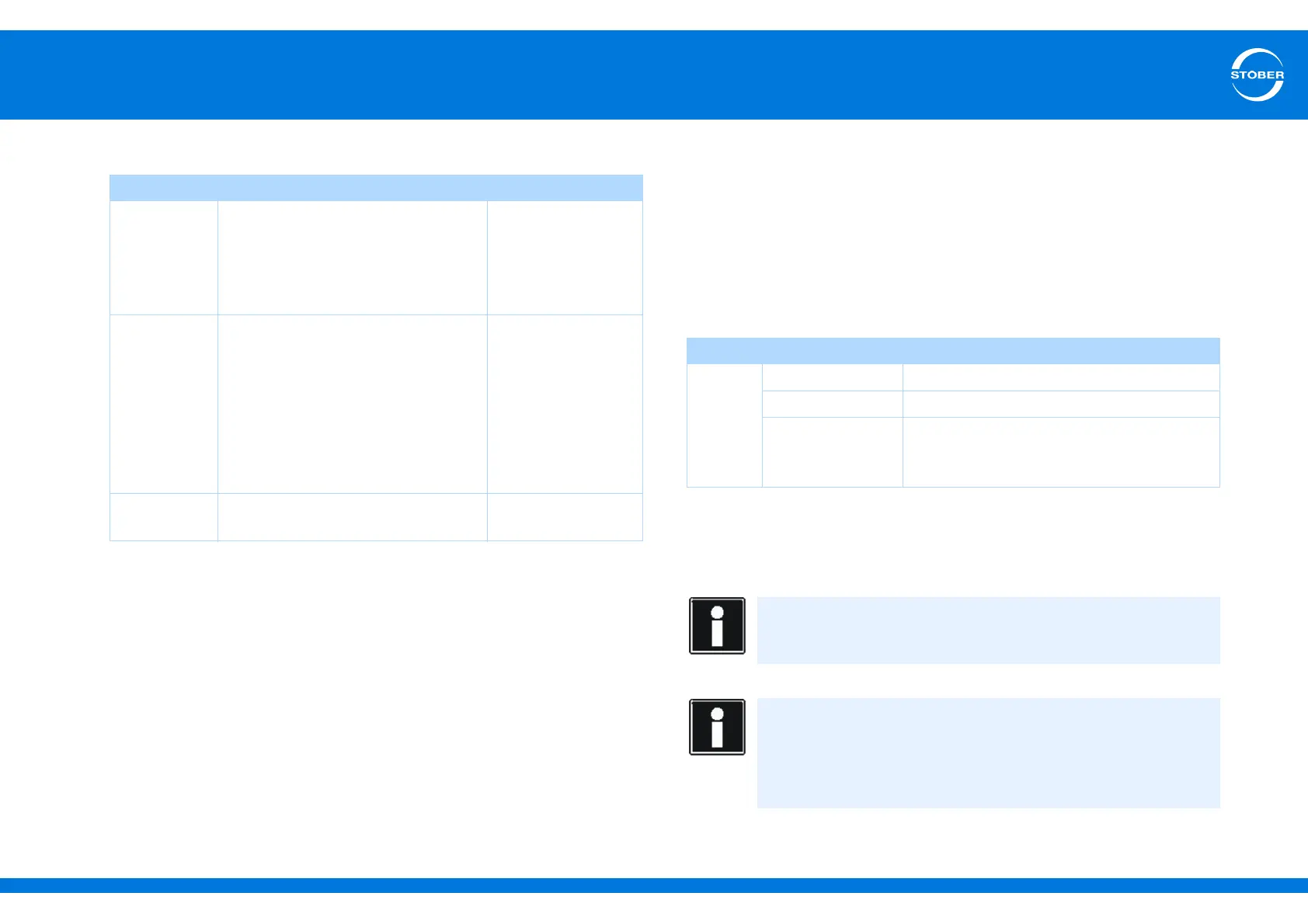
Electrical data
Brake
U
1
24–30 V
I
1max
3.0 A
Maximum
switching
frequency
1 Hz
Information
Before using a KTY, note that motor protection is not ensured to the
same extent as when monitoring with PTC drilling.
Information
Note that evaluation of the temperature sensors is always active. If
operation without temperature sensor is permitted, the connections
must be bridged on X2. Otherwise a fault will be triggered when the
device is switched on.