ID 442426.04 97WE KEEP THINGS MOVING
Connection
7
Manual SD6
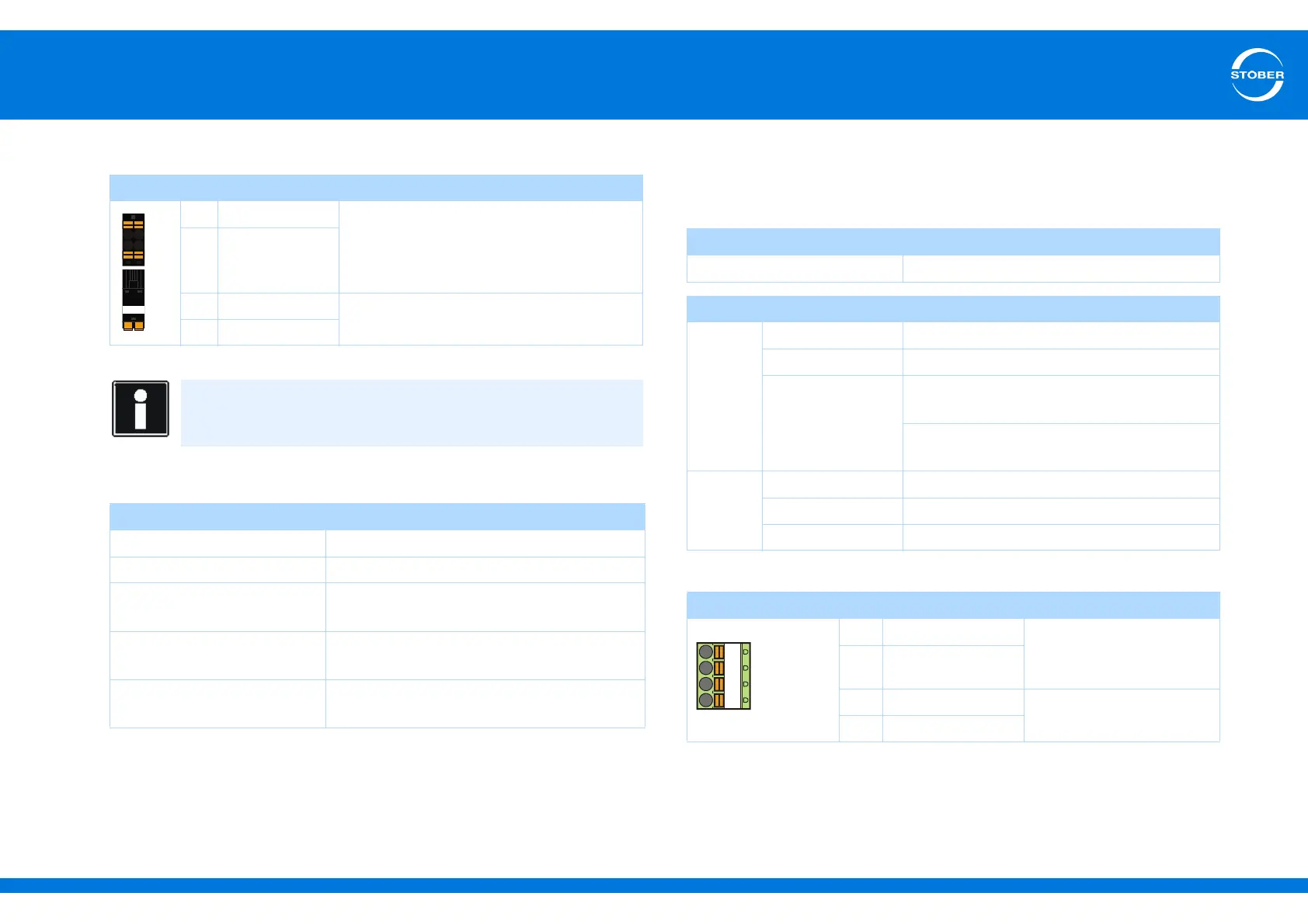
Terminal description X11
Maximum conductor cross-section
7.3.4 X1: Enable and relay 1
Use the enable signal to enable the power pack of the drive controller. The
function of relay 1 can be adjusted in parameter F75.
Terminal description X1
Pin Designation Function
++ 24 V 24 V
DC
supply of the control unit, design
according to EN 60204:
PELV, secondary earthed,
max. line length 30 m
++ 24 V
–GND
Reference potential for 24 V; bridged in the
terminal
–GND
Information
The drive controller may not be connected to a DC mains supply.
Instead supply the drive controller via a local 24 V
DC
power supply.
Connection type Maximum conductor cross-section [mm
2
]
Rigid 2.5
Flexible 2.5
Flexible with cable end,
without plastic sleeve
2,5
Flexible with cable end, with
plastic sleeve
2,5
2 leads with the same cross-
section with double cable end
—
General specification
Maximum cable length 30 m
Electrical Data
Relay 1
U
2max
30 V
I
2max
1,0 A
Life expectancy Mechanical: min. of 5,000,000 switching
operations
At 24 V/1A (ohmic load): 300,000 switching
operations.
Enable
High level 12–30 V
Low level 0–8 V
I
1max
16 mA
Pin Designation Function
1 Contact 1 Relay 1
Recommended fuse: max.
1 AT
a)
a) Use a 1 A fuse (delayed-action) upstream from relay 1 for fuse protection. Make certain for UL-
compliant operation that the fuse has been approved for the requirements of UL 248.
2 Contact 2
3GND
Enable
4 Input