ID 442426.04 251WE KEEP THINGS MOVING
Encoder
12
Manual SD6
12.3 Selecting an interface
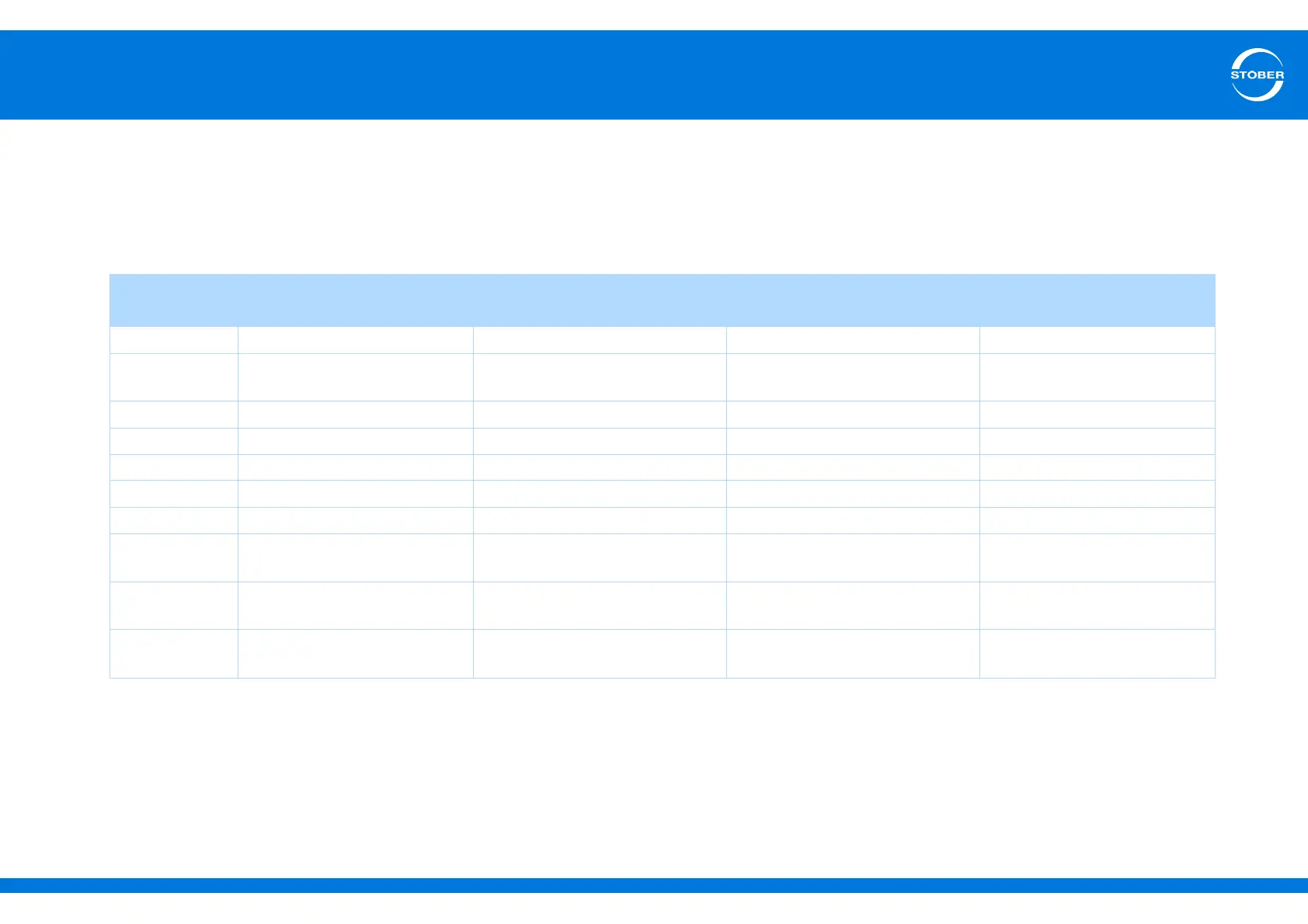
The table below gives you a summary of which encoder signals can be evaluated on which interface. The header that belongs to the interface contains the setting
of B26 motor encoder and I02 position encoder. The cells indicate the setting with which you will parameterize encoder signals that will be evaluated on the interface.
Note that other settings must also be made for the encoder signals to be evaluated correctly. The settings are described in sections 12.4 Connection X4 to 12.6
Connection X101 (binary input encoder).
Encoder
signals
X4 X120
a)
a) Only with one of terminal modules XI6, RI6
X140
b)
b) Only with terminal module RI6
X101
c)
c) Only with one of terminal modules XI6, RI6, IO6
B26/I02 = 2:X4 encoder B26/I02 = 4:X120 encoder B26/I02 = 3:X140 encoder B26/I02 = 1:BE encoder
EnDat® 2.2 H00 = 64:EnDat — H140 = 70:EnDat —
EnDat® 2.1 H00 = 64:EnDat —
H140 = 71:EnDat with sin/cos
channels
—
SSI H00 = 65:SSI master H120 = 67:SSI master ——
Resolver — — H140 = 66:Resolver —
Sin/cos — — H140 = 6:Sin/cos —
Hall sensor — H120 = 70:Hall sensor ——
Incremental HTL H00 = 3:Incremental encoder In ——H40 = 1:Incremental encoder In
Incremental TTL
H00 = 3:Incremental encoder In H120 = 4:Incremental encoder In
—
H40 = 1:Incremental encoder In
b)
Stepper motor
HTL
—— —H40 = 5:stepper motor
Stepper motor
TTL
—
H120 = 5:stepper motor input
— H40 = 5:stepper motor
b)