Virtex-6 FPGA GTX Transceivers User Guide www.xilinx.com 157
UG366 (v2.5) January 17, 2011
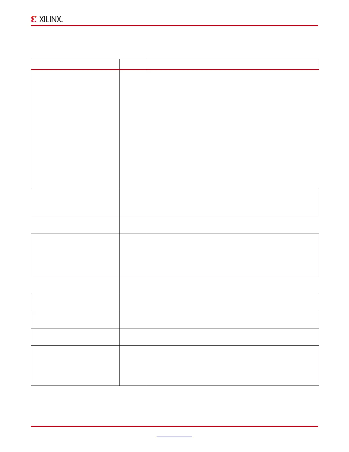
TX Buffer Bypass
Table 3-19 defines the TX buffer bypass attributes.
Table 3-19: TX Buffer Bypass Attributes
Attribute Type Description
POWER_SAVE 10-bit
Binary
POWER_SAVE[4]:
Mux select for the TXOUTCLK output clock. Must be tied to 1’b1.
1'b0: Use the TX Delay Aligner
1'b1: Bypass the TX Delay Aligner
POWER_SAVE[5]:
Mux select for the RXRECCLK output clock. Must be tied to 1’b1 when
RX buffer is used (RX_BUFFER_USE = TRUE). When RX buffer is
bypassed, refer to Using the RX Phase Alignment Circuit to Bypass the
Buffer, page 235.
1'b0: Use the RX Delay Aligner
1'b1: Bypass the RX Delay Aligner
All other bits are reserved. Use recommended values from the Virtex-
6 FPGA GTX Transceiver Wizard.
TX_BUFFER_USE Boolean Use or bypass the TX buffer.
TRUE: Use the TX buffer (normal mode).
FALSE: Bypass the TX buffer (advanced feature).
TX_BYTECLK_CFG[5:0] 6-bit Hex Reserved. Use only recommended values from the Virtex-6 FPGA GTX
Transceiver Wizard.
TX_DATA_WIDTH Integer Sets the transmitter external data width
8/10: 1-byte interface
16/20: 2-byte interface
32/40: 4-byte interface
If 8B10B is used, this attribute must be a multiple of 10.
TX_DLYALIGN_CTRINC 4-bit
Binary
Reserved. Use only recommended values from the Virtex-6 FPGA GTX
Transceiver Wizard.
TX_DLYALIGN_LPFINC 4-bit
Binary
Reserved. Use only recommended values from the Virtex-6 FPGA GTX
Transceiver Wizard.
TX_DLYALIGN_MONSEL 3-bit
Binary
Reserved. Use only recommended values from the Virtex-6 FPGA GTX
Transceiver Wizard.
TX_DLYALIGN_OVRDSETTING 8-bit
Binary
Sets the overdrive value for the TX delay aligner. This attribute takes
effect when TXDLYALIGNOVERRIDE is driven High.
TX_PMADATA_OPT 1-bit
Binary
This attribute controls the inverter that optimizes the clock path within
the GTX transceiver for different mode of operations. The attribute
must be set as follows:
0: Use when TX_BUFFER_USE = TRUE
1: Use when TX_BUFFER_USE = FALSE

 Loading...

