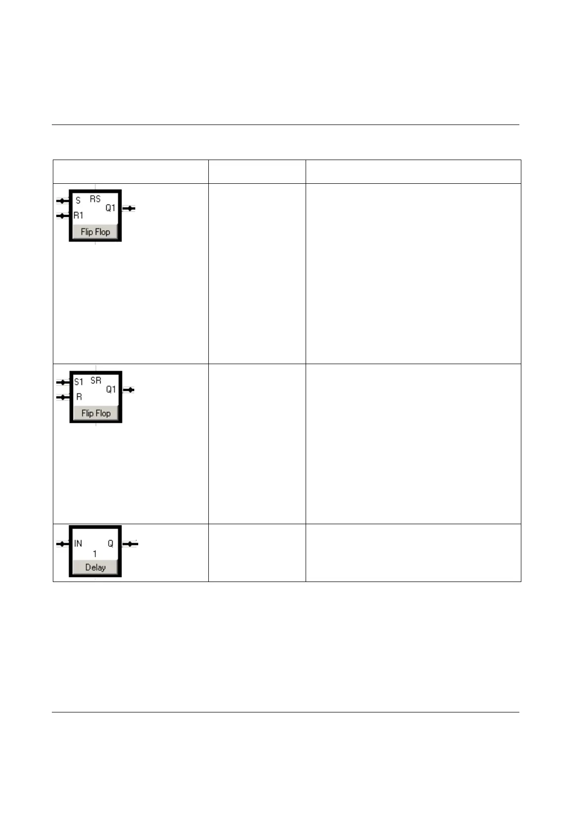
The Flip Flop gate is also called latch or bi-stable relay
and acts like a memory. R and S stand for Reset and Set.
The stored bit is present on the output marked Q1.
If S receives a positive flank (transition low to high) while
R1 is low, then the Q1 output goes high, and stays high
when S returns low.
If R1 goes high while S is low, then the Q1 output goes
low, and stays low when R1 goes inactive.
If S goes high while R1 is high, then the output Q1
remains low since priority is given to the R1 input.
If S1 receives a positive flank while R is low, then the Q1
output goes high, and stays high when S1 returns low.
If R goes high while S1 is low, then the Q1 output goes
low, and stays low when R returns low.
If R goes high while S1 also is high, then the Q1 output
remains high since priority is given to the S1 input.
The Delay is implemented as a shift register. It has a
preset timer (delay time) multiple with the PLC tick.
PT stands for Preset Time and is configurable.
 Loading...