3-10
Chapter 3. Wiring
Handling Precautions
• Connect a terminating resistor (120 Ω, 1/2 W) to both ends of the
communication line. Do not connect a terminating resistor to the middle part
of the communication line.
• To connect two terminals together such as SG, use a crimp terminal without
an insulation sleeve.
• Be sure to connect the SG terminals to each other. Failure to do so might cause
unreliable communication.
• If equipment controller devices that do not allow connection of a terminating
resistor (such as Azbil Corporation's SDC15/25/26/35/36 and DMC10) are
included in the transmission line, do not connect any terminating resistor to
the external or communication lines of the C7G.
• The frame ground should be connected to only one end of the shielded cable,
not to both ends.
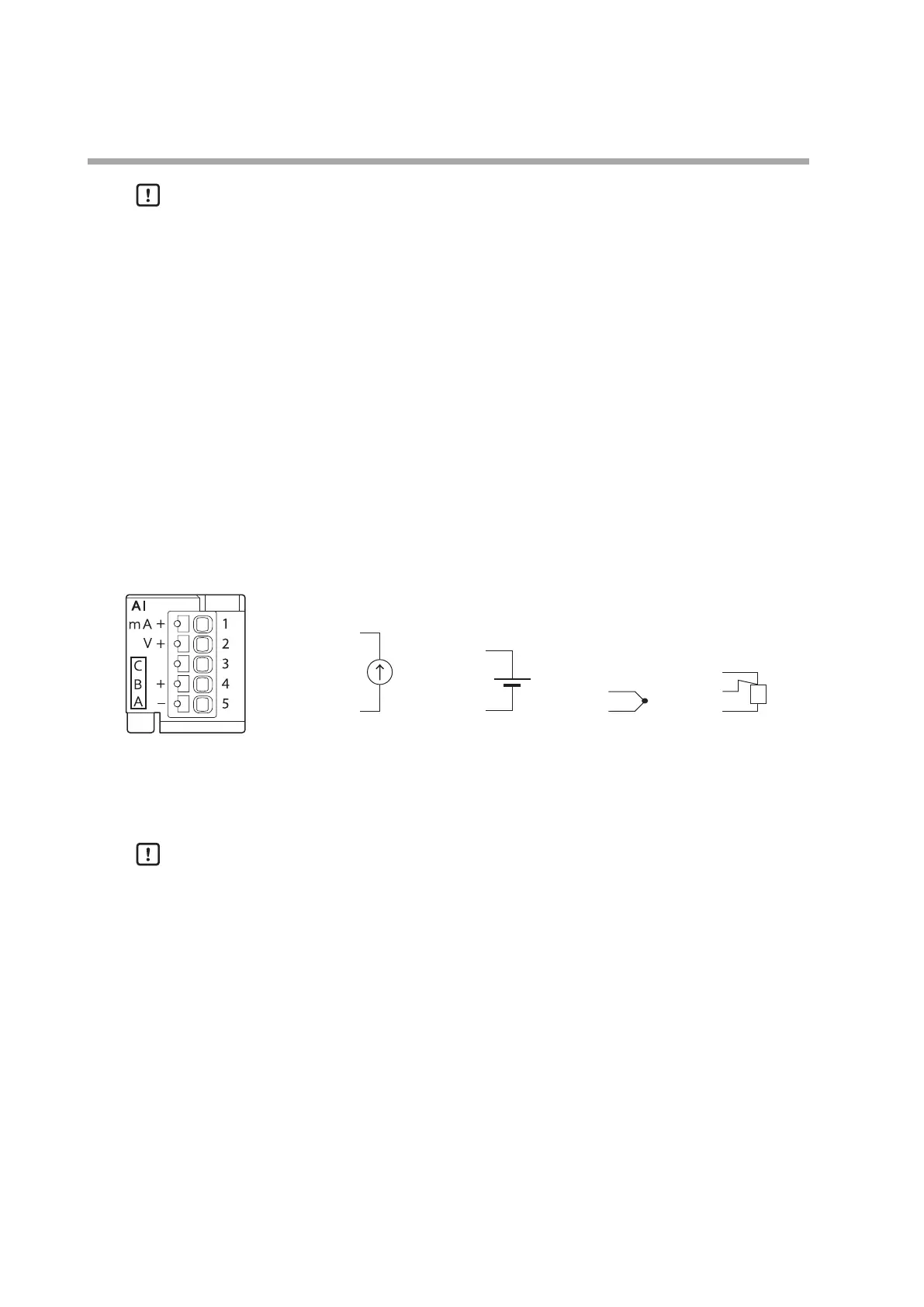
Analog input block (analog input)
V+
−
+
-
B
C
A
mA+
Current input Voltage input T/C input RTD input
1 :
2 :
3 :
4 :
5 :
1 :
2 :
3 :
4 :
5 :
1 :
2 :
3 :
4 :
5 :
1 :
2 :
3 :
4 :
5 :
-
Maximum allowable input voltage
Current input: –1.5 to +1.5 V
Voltage input: –15 to +15 V
T/C input: –1.5 to +1.5 V
Handling Precautions
• Do not apply a voltage exceeding the allowable maximum input stated in the
specifications to any input. Doing so will cause device failure.
• Make the connections while carefully checking the polarity of the inputs.
• Use shielded cables for input wiring.
• When a thermocouple is used for the input, take appropriate measures so that
no terminals are exposed to moving air. Failure to do so may result in an error.
• Set a suitable sensor type for usage. If the setting is incorrect, it will not be
possible to measure the PV correctly, and a hazardous situation could result,
such as a constant 100 % control output.