14-22
Chapter 14. Appendix
Description User's Manual Reference User's Manual Change
Changed so that the alarm is not reflected
when the display unit is not connected
1 - 3 Names of Parts and Their
Functions
Main unit (p.1-8) Status indicator
Not changed
11 - 2 Alarm
Block alarm (p.11-3)
Changed the displayed content in the
function alarm screen
11 - 2 Alarm
Function alarm screen (p.11-5)
Changed CT/VT to CT/VT (AO-C)
Added CT (V-P), BATTERY
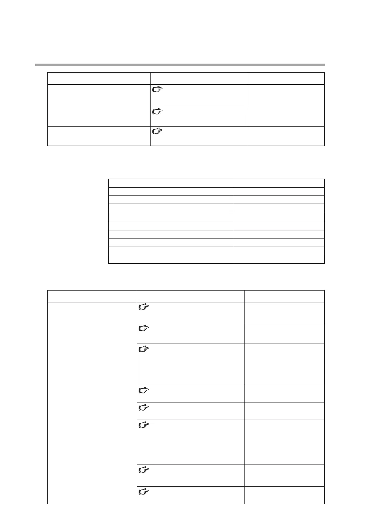
Support start date: August 2017
Block Firmware version (X is 0 to 9)
MAIN block 5.0.X
HMI block (display unit, additional display unit) 5.0.X
DI/DO block 3.0.X
RS-485 block 3.0.X
AO-C block (slots A1 to A2, B1 to B2) 3.0.X
V-P block (slots A1 to A2, B1 to B2) 1.0.X
AI block (slots A3 to A4, B3 to B4) 3.0.X
CLOCK block (slot B1) 1.0.X
MOTOR block (slot B2) 1.0.X
Added functions
Description User's Manual Reference User's Manual Change
Support for MOTOR block
1 - 2 Model No.
Model Selection Guide (p.1-2)
Added a table for the motor
drive model Nos.
1 - 3 Names of Parts and Their Functions
Main unit (p.1-8)
Added Motor Drive to the block
layout example
1 - 4 Input/output Configuration
Input and output configuration diagram
(p.1-9)
Motor drive output (MOTOR) (block position:
B2) (p.1-9)
Added motor drive output
1 - 5 Button Operation
Screen transitions (p.1-11)
Added “PV, SP, MV, MFB (MOTOR
block)” to the monitor screen
1 - 5 Button Operation
Parameter bank (p.1-12)
Added PP (position
proportioning)
5 - 1 Monitor Screen and Graph Screen
1-loop monitor screen when MFB AT is
stopped (p.5-20)
1-loop monitor screen during MFB AT
(p.5-21)
Added the content at left
5 - 1 Monitor Screen and Graph Screen
Block alarm screen (p.5-24)
Added a description of block
type = motor drive output,
display = MOTOR
5 - 2 Parameter screen
Firmware Versions (p.5-52)