2-1
Chapter 2. Mounting
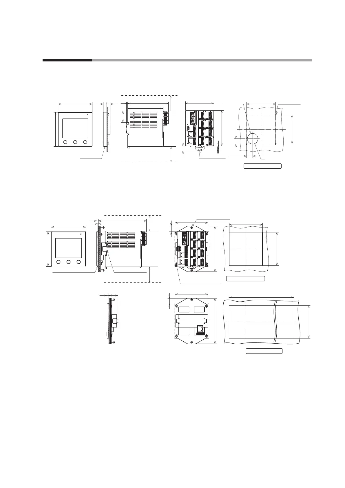
2 - 1 External View and Mounting Dimensions
Standard mounting
Unit: mm
96
96 10
9.2
(3.6)
(13)
100
5
115
80
4×Φ3.6
±0.2 Hole
Φ30
Hole
+1.5
−0
100.5
32.3
Standard gasket
50 or more
Other device
50 or more
Other device
Display unit
Main unit
DIN rail holder *
* Dimensions when pulled out
82 ±0.2
14.6
±0.3
17.3
±0.3
82
±0.2
Panel cutout (front)
Panel processing method
Wiring hole
Integrated mounting
Unit: mm
91.4
91.4
15
15
126
126
Integrating bracket
50 min.
Other devices
50 min.
Other devices
Display unit Main unit
96
96
134
4.7
2
4.7
26.5
92
Hole
+0.5
−0
92
Hole
+0.5
−0
Main unit mounting rail
Display unit mounting screw
(4 locations)
Control panel mounting
screw (2 locations)
Panel processing method
Gasket with 92 × 92 mm hole
Panel cutout (front)
96 × N − 4
Hole
+0.5
−0
92
Hole
+0.5
−0
Panel processing method
Independent mounting
Gang mounting
Mounting locations
Do not install this product in a place with any of the following characteristics:
• Temperature or humidity outside the specified high and low limits
• Corrosive gases such as sulfide gas or silicone gas
• Dust or soot
• Direct sunlight, wind, or rain
• Mechanical vibration or shock outside the range of the specifications
•
Proximity to high-voltage lines, welding machines, or other sources of electrical noise
• Within 15 m of a high-voltage ignition device for a boiler, etc.
• Strong electromagnetic fields
• Flammable liquid or gas
• Outdoor location