9-13
Chapter 9. User-defined Addresses
Reception can be monitored for Modbus RTU (RS-485) or Modbus TCP (Ethernet) read instruction messages or
write instruction messages for up to three user-defined addresses.
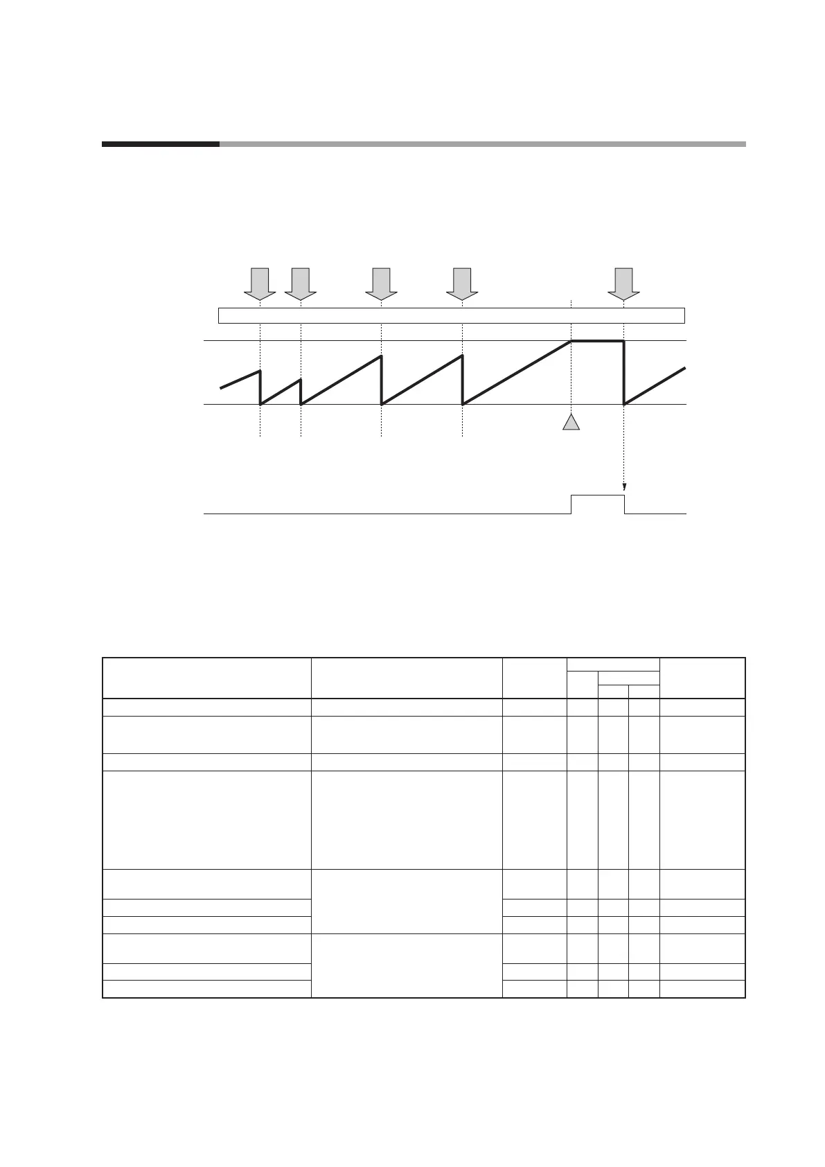
The figure below illustrates the process when reception is monitored for both reading and writing for one user-
defined address.
Timeout time
Data write
0
Reception monitoring (standard bit)
Data read Data write Data read Data write
Occurrence of error
User-dened address being monitored
ON
OFF OFFOFF
Reception monitoring settings
Reception monitoring can be set using the SLP-C7 Smart Loader Package. The
settings cannot be configured from a display unit. When the reception monitoring
function is assigned to a user-defined address, settings can be configured from the
host device via communication.
Item Settings
Initial
value
Communication
Notes
Read
Write
RAM EEP
Reception monitoring start delay time 0 to 1000 s 0
# *
Reception monitoring 1 monitoring
address
0: Not used
1 to 49999: User-defined address
0
# *
Reception monitoring 1 time-out time 1 to 3600 s 180
# *
Reception monitoring 1 mode 0: Without reception monitoring
1: With read reception monitoring
2: With write reception monitoring
3: With both read and write
reception monitoring
0
# *
Reception monitoring 2 monitoring
address
Same as reception monitoring 1 0
# *
Reception monitoring 2 time-out time 180
# *
Reception monitoring 2 mode 0
# *
Reception monitoring 3 monitoring
address
Same as reception monitoring 1 0
# *
Reception monitoring 3 time-out time 180
# *
Reception monitoring 3 mode 0
# *
9 - 4 Reception Monitoring