3-15
Chapter 3. Wiring
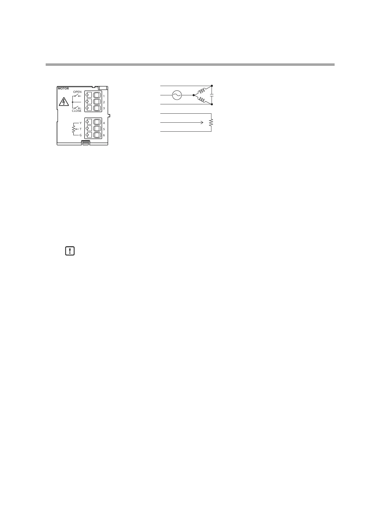
MOTOR block (motor drive outputs and motor feedback inputs)
1: OPEN
2: Common
3: CLOSE
4: MFB (Y)
5: MFB (T)
6: MFB (G)
Contact rating
For models other than UL-compliant models
2 A, 250 V AC (inductive load)
2.5 A, 24 V DC (inductive load)
For UL-compliant models
2 A, 250 V AC (general use)
FLA: 2 A, 240 V AC (100 W)
Potentiometer for motor feedback
100 to 2500 Ω
Handling Precautions
• If a motor with a 100/200 V AC motor power supply is used, pay careful
attention to both the contact rating and the inrush current, and if necessary,
use an external auxiliary relay.
• Do not route the wires of the MOTOR block output terminals (1, 2, and 3)
through the same duct as the wires of the MOTOR block MFB input terminals
(4, 5, and 6).
Also, do not put 6-core cables together. Otherwise, the device could fail due to
noise at motor startup.
• If the "Control method selection" setting of the PP (position proportional)
bank is 2 (estimated position control) or 3 (estimated position control +
position adjustment at power-on), the wires for the MOTOR block MFB
terminals 4, 5, and 6 are not needed (when controlling without motor
feedback).
• Set MOTOR block output terminal 3 for motor CLOSE output.
If output terminal 3 is set to OPEN output, the motor output may be stuck at
OPEN if the relay fails.
• UL-compliant models cannot be used with the 24 V DC contact rating.
Close
Open
Close
Open