3-14
Chapter 3. Wiring
• When the current transformer input is used for phase angle control, the input
accuracy of the product may not be satisfied.
• If a current transformer is used for a UL-compliant model, the transformer
must be compliant with UL 2808 (categories XOBA and XOBA7). Do not use an
uncertified current transformer.
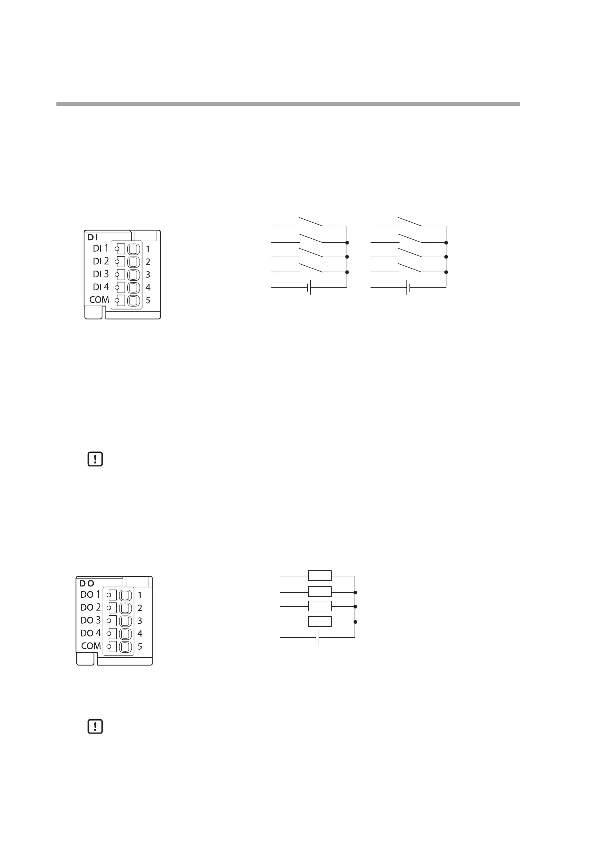
DI block (4 digital inputs)
1: Digital input 1
2: Digital input 2
3: Digital input 3
4: Digital input 4
5: Common
Rated input voltage:
24 V DC +20/−15 %
Terminal current:
4 mA (with 24 V DC input)
ON voltage/current :
19 V or more / 3 mA or more
OFF voltage/current:
7 V or less / 1 mA or less
Handling Precautions
• Gold contacts, etc., suitable for turning a microcurrent ON or OFF should be
used for contacts.
• When a semiconductor is used as a contact, use a semiconductor with an OFF-
state leakage current within the allowable limits.
DO block (4 digital outputs, sink output)
1: Digital output 1
2: Digital output 2
3: Digital output 3
4: Digital output 4
5: Common
Load voltage:
4.5 to 28 V DC
Load current:
100 mA max. per digital output
Handling Precautions
• An overcurrent protection circuit is incorporated. If an overcurrent is detected,
the DO is forced OFF and an alarm is generated. The status of the loads is
checked every 5 seconds after an overcurrent has been detected. When the
overcurrent status is canceled, the DO is restored automatically.
24 V DC 24 V DC
5
to
24 V DC