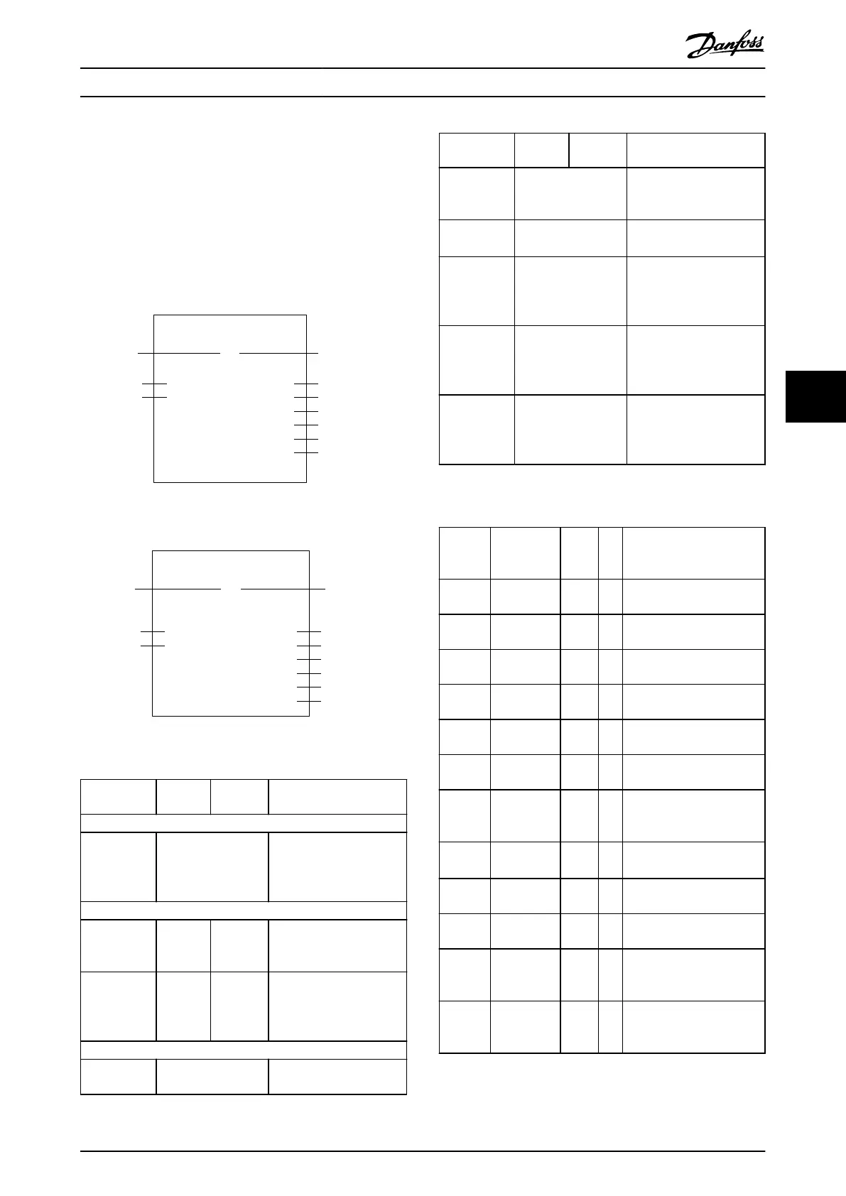
6.5.4.18 MC_ReadParameter_ISD51x and
MC_ReadBoolParameter_ISD51x
This function block returns the value of the specied
parameter. The time taken until valid data is available at
the output depends on several factors, for example:
•
PLC system
•
Cycle times
•
Amount of acyclic data requested
MC_ReadParameter_ISD51x
Axis
EnableBOOL
ParameterNumberINT
AXIS_REF_-
ISD51x
BOOLValid
BOOLBusy
BOOL
DD_ERROR_ISD51x
ErrorInfo
DWORD
AbortCode
DWORD
Value
Error
130BE298.10
Illustration 6.41 MC_ReadParameter_ISD51x
MC_ReadBoolParameter_ISD51x
Axis
EnableBOOL
ParameterNumberINT
AXIS_REF_-
ISD51x
BOOLValid
BOOLBusy
BOOL
DD_ERROR_ISD51x
ErrorInfo
DWORD
AbortCode
BOOL
Value
Error
130BE294.10
Illustration 6.42 MC_ReadBoolParameter_ISD51x
Variable
name
Data
type
Default
value
Description
VAR_IN_OUT
Axis AXIS_REF_ISD51x Reference to the axis.
See
chapter 6.5.4.1 AXIS_REF_IS
D51x.
VAR_INPUT
Enable BOOL FALSE Get the value of the
parameter continuously
while enabled.
Parameter-
Number
INT 0 Number of the parameter.
See Table 6.20. All other
numbers are not allowed
and lead to an error.
VAR_OUTPUT
Valid BOOL The function block has a
valid output.
Variable
name
Data
type
Default
value
Description
Busy BOOL The function block is not
nished and new output
values are to be expected.
Error BOOL An error has occurred
within the function block.
ErrorInfo DD_ERROR_ISD51x Error identication and
instance identier.
See chapter 6.5.2.3 Error
Indication.
AbortCode DWORD SDO abort code if there is
an error. Available in the
list of constants:
SdoAbortCodes.
Value DWORD/BOOL Value of the specied
parameter in the data
type, as specied in
Table 6.20.
Table 6.19 MC_ReadParameter_ISD51x and
MC_ReadBoolParameter_ISD51x
Para-
meter
Number
Name Data
type
R/
W
Description
1 Comman-
dedPosition
DINT R Commanded position
2 SWLimitPos DINT R/
W
Positive software limit
switch position
3 SWLimitNeg DINT R/
W
Negative software limit
switch position
4 EnableLi-
mitPos
BOOL R Enable positive software
limit switch
5 EnableLi-
mitNeg
BOOL R Enable negative software
limit switch
7 MaxPosi-
tionLag
UDINT R/
W
Maximum position lag
8 MaxVelocity-
System
REAL R Maximum allowed velocity
of the axis in the motion
system
9 MaxVeloci-
tyAppl
UDINT R/
W
Maximal allowed velocity of
the axis in the application
10 ActualVe-
locity
DINT R Actual velocity
11 Comman-
dedVelocity
DINT R Commanded velocity
13 MaxAcceler-
ationAppl
UDINT R/
W
Maximal allowed
acceleration of the axis in
the application
15 MaxDeceler-
ationAppl
UDINT R/
W
Maximal allowed
deceleration of the axis in
the application
Table 6.20 Parameters for MC_ReadParameter_ISD51x,
MC_ReadBoolParameter_ISD51x and MC_WriteParameter_ISD51x
Programming Programming Guide
MG36D102 Danfoss A/S © 01/2017 All rights reserved. 187
6
6

 Loading...


