Dynon Avionics does not sell a tachometer transducer.
Depending upon existing equipment and engine type, you have a few options for
connecting the tachometer inputs on the SV-EMS-220. Table 15 revisits the SV-EMS-220
pins that are compatible with RPM sources.
Table 15: SV-EMS-220 RPM Inputs
See the relevant subsections below for your particular method. You may connect different
types of signals to the two (2) different RPM inputs (e.g., p-lead to Standard RPM Left
and a 12 volt transducer to Standard RPM Right).
SkyView will display RPM from either the RPM Input Left or the RPM Input Right,
whichever is noticed by the SV-EMS-220 first. If the first RPM signal is lost (such as when
one (1) ignition source fails, or during a routine mag check), then SkyView will display
RPM from the remaining RPM signal. If your engine only provides one (1) RPM signal,
connect it to one (1) of the two (2) RPM Input Left pins.
10.2.9.1 Tachometer transducer
If you have a dedicated tachometer transducer (usually with a 12 volt output), you may
simply connect its output to the Standard RPM Left input on the SV-EMS-220. Ensure
that you follow all recommendations given in the manual for your individual tachometer
transducer.
10.2.9.2 P-lead pickoff (Lycoming and Continental)
If you do not have a dedicated tachometer pickoff, you
must follow the instructions below.
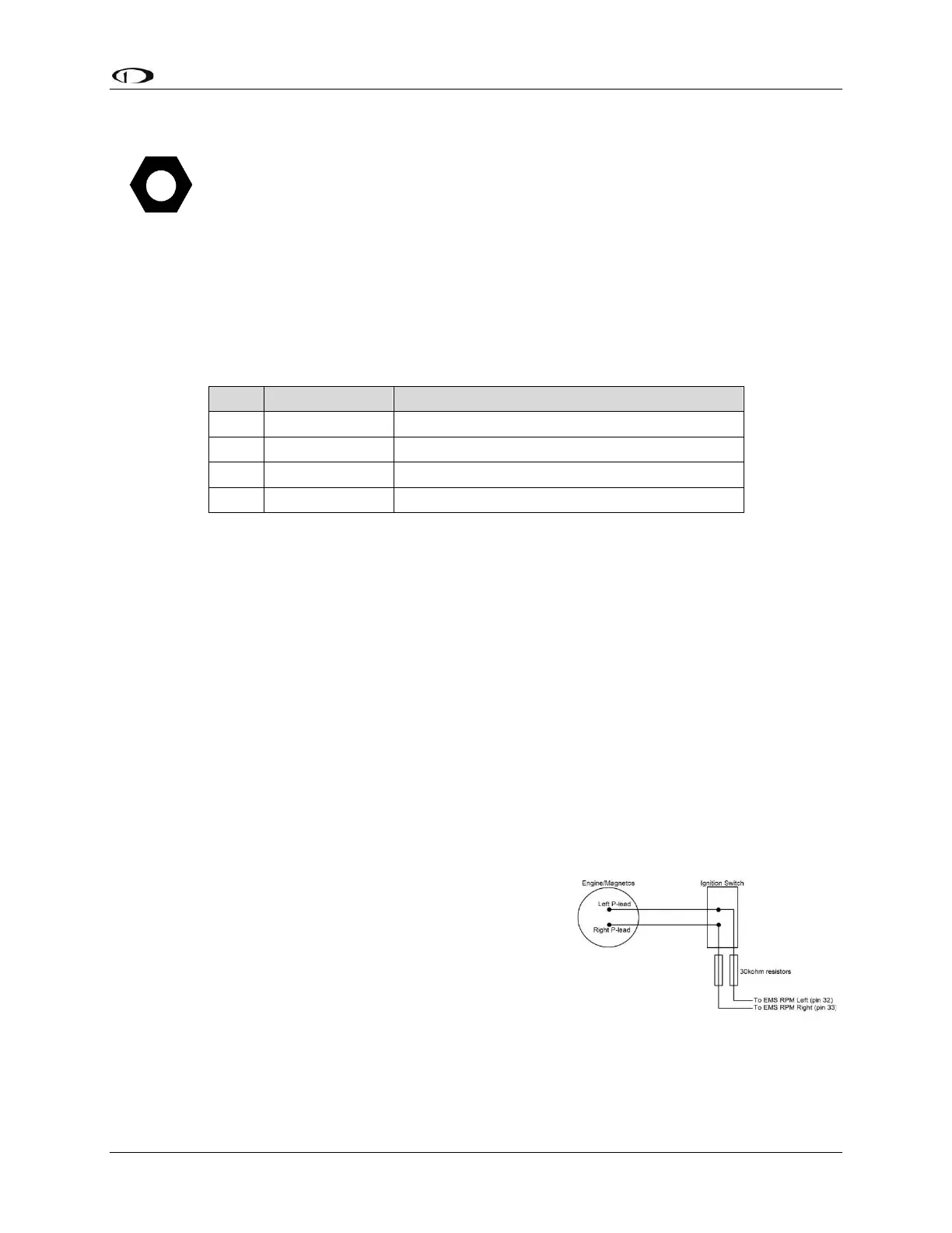
Use the two (2) included 30 kΩ resistors (color bands:
orange, black, brown, red, brown; connect in either
direction) to attach left and right P-leads to the standard
RPM Left and RPM Right inputs on the SV-EMS-220.
Connect them as shown in the figure to the right. It is
important to connect each resistor as close as possible
to the spot where you tap into the P-lead. This
minimizes the length of cable carrying high voltage spikes. Six (6)-cylinder Lycoming
engines sometimes need more inline resistance to prevent false readings by the SV-EMS-