SV-ADSB-472 ADS-B IN Receiver Installation and Configuration
SkyView HDX System Installation Manual - Revision E 14-9
• Route the cable away from sources of heat.
• Route the cable away from potential interference sources such as ignition
wiring, 400Hz generators, fluorescent lighting, and electric motors.
• Keep the cable run as short as possible.
• Avoid routing the cable around tight bends.
• Avoid kinking the cable even temporarily during installation.
• Secure the cable so that it cannot interfere with other systems.
14.3.3 Antenna BNC Female Connector
This section describes the technique for attaching the antenna cable to a BNC Male
connector. A BNC Male connector is not supplied with the SV-ADSB-472. The SV-ADSB-
472 has a BNC Female connection. Therefore, you will need to source a BNC Male
connector that is compatible with the antenna cable type that meets your aircraft’s needs.
A dual crimp style BNC connector can be completed using a wide range of commercial
crimp tools (for example the Tyco 5-1814800-3). The die apertures for the inner pin and
the outer shield should be approximately 0.069 inches (1.72 mm) and 0.213 inches (5.41
mm) respectively.
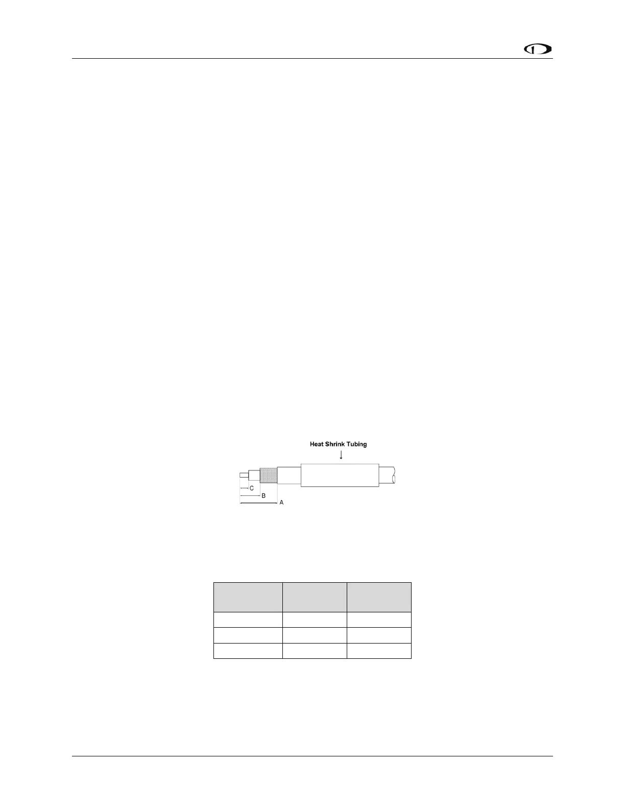
• Strip back the coax cable to the dimensions in the table, as shown in the
diagram below. Slide 1 inch (25.4 mm) of heat shrink tubing over the cable.
• Slide the outer crimp sleeve over the cable – it must go on before securing the
center contact.
Figure 99: ADSB-472 COAX
Table 38: Example figure of a dual crimp style BNC connector
• Crimp the center contact to the cable.
• Insert the cable into the connector – the center contact should click into place
in the body, the inner shield should be inside the body of the connector and the
outer shield should be outside the body.