SV-XPNDR-261 Transponder Installation and Configuration
SkyView HDX System Installation Manual - Revision E 12-13
A dual crimp style TNC connector can be completed using a wide range of commercial
crimp tools (for example the Tyco 5-1814800-3). The die apertures for the inner pin and
the outer shield should be approximately 0.067 inches (1.72 mm) and 0.213 inches (5.41
mm) respectively.
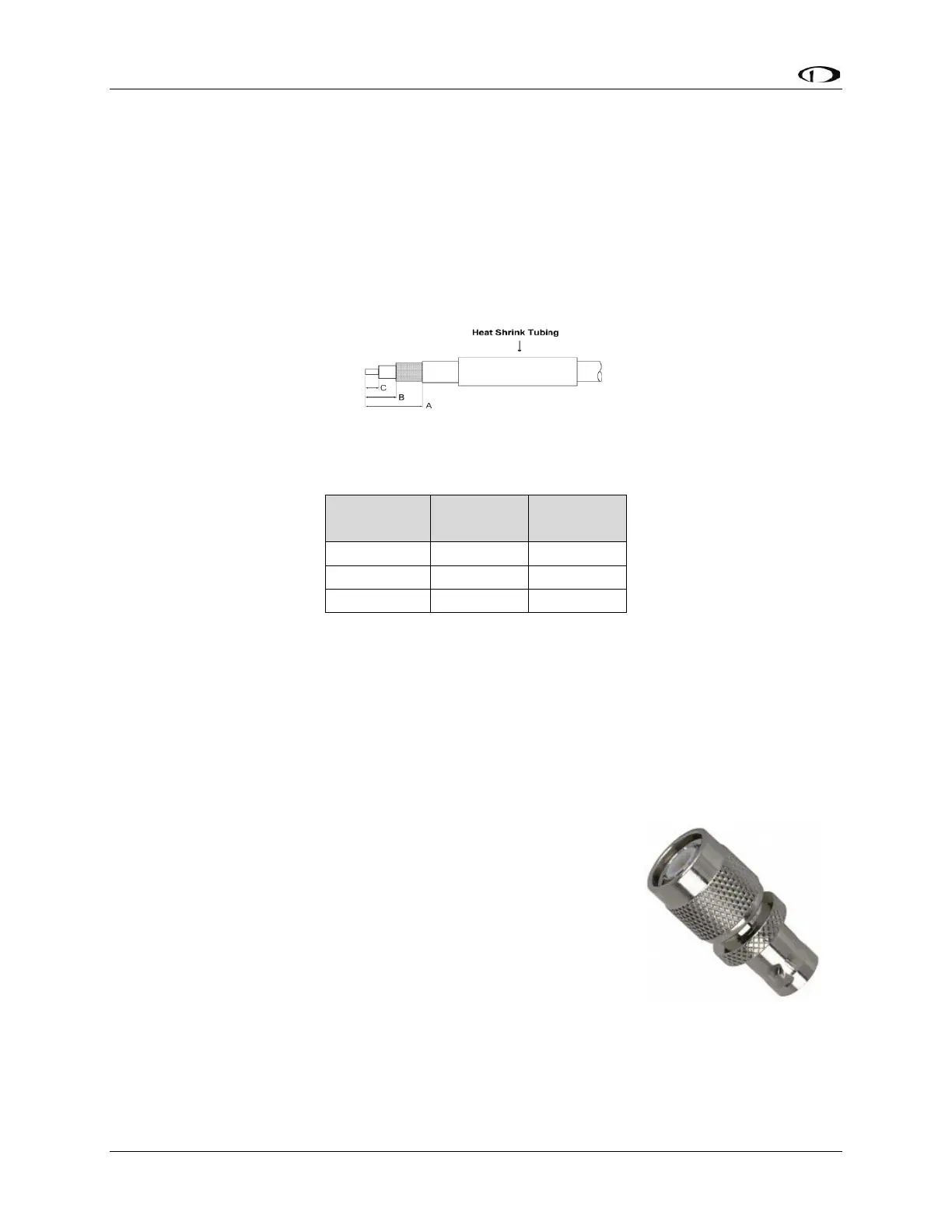
• Strip back the coax cable to the dimensions in the table, as shown in the
diagram below. Slide 1 inch (25.4 mm) of heat shrink tubing over the cable.
• Slide the outer crimp sleeve over the cable – it must go on before securing the
center contact.
Figure 78: Transponder COAX Cable
Table 32: Coaxial Cable Strip Dimensions
• Crimp the center contact to the cable.
• Insert the cable into the connector – the center contact should click into place
in the body, the inner shield should be inside the body of the connector and the
outer shield should be outside the body.
• Crimp the outer sleeve over the shield.
• Slide heat shrink tubing forward (flush to connector) and heat to shrink the
tubing.
12.2.12 TNC to BNC Adapter
If you have purchased a transponder antenna that has coaxial
cable and a BNC connector already installed, you can use a
“Male TNC to Female BNC” adapter to adapt the SV-XPNDR-
261’s TNC connector to a BNC Female connector. As this
adapter will be used for transmitting radio frequency energy
above 1 GHz, we recommend that you purchase an adapter by
a reputable manufacturer of radio frequency connectors and
adapter such as Amphenol. The part pictured at right is an
Amphenol P/N 242149, and is available from Digi-Key as P/N
ACX1378-ND.