. This initially causes some confusion because the
same type of connector is used for “RS-232 serial” on PCs and other
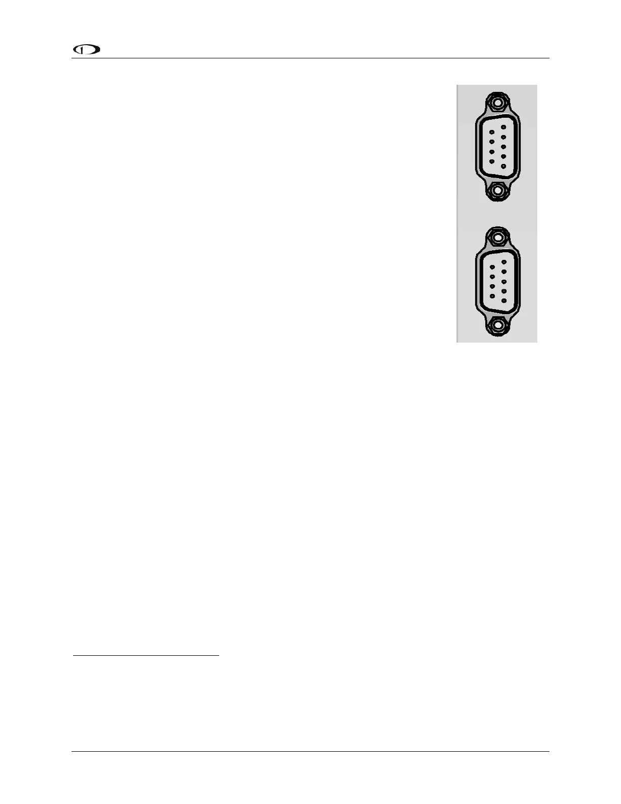
(non-SkyView) devices, such as GPS units. The 9-pin SkyView
Network connectors on the back of a SkyView display are shown in
Figure 9 at right.
The specific use of the various pins within the 9-pin SkyView Network
connectors in a SkyView system is unique to SkyView. It is important
to understand that in SkyView, the 9-pin connectors are not
electrically compatible with RS-232 serial connections found on
PCs and other devices. One (1) critical difference is that in a
SkyView Network 9-pin D9F or D9M connector, 3 of the 9 pins
provide power, which, if connected to a RS-232 serial device,
could damage it, or damage the SkyView display. For example, if
you wish to connect a GPS unit that has an RS-232 output, it will not
work and may damage the SkyView or GPS unit. Connect the two (2)
units directly by plugging the GPS’ 9-pin connector into the 9-pin
connectors on the SkyView display.
RS-232 serial devices can be connected to a SkyView system. This
is done via specific pins / wires of the SV-HARNESS-D37 37-pin
connector / harness on the SkyView display. Details of connecting RS-232 serial devices
are explained in Section 2.11, and Section 25: Appendix C: Wiring and Electrical
Connections.
The SkyView Network communicates between the displays and modules as a modern,
multi-drop (serial BUS) network, similar to an old-fashioned telephone party line. A more
modern example of a multi-drop serial network is Ethernet. The SkyView Network wiring
is electrically common between all SkyView Network devices. In the SkyView Network
each Pin 1 of the 9-pin SkyView Network connectors and cables are electrically
connected to every SkyView Network 9-pin connector Pin 1.
The “physical” method of each connection doesn’t matter – electrical connections can be
made with splitters, hubs, multiple SkyView Network connectors on the back of a device
(both connectors are electrically common), etc. All SkyView Network devices “listen” on
the SkyView Network. A SkyView display manages (controls) all communications over
the SkyView Network. For example, if there are two SV32 servos installed, the SkyView