Appendix C: Wiring and Electrical Connections
SkyView HDX System Installation Manual - Revision E 25-17
Table 74: SV-AP-PANEL D15M Connector
(determined by
installer)
If trim motor(s) control is not used, do not
connect. Power and ground for the SV-AP-
PANEL front panel buttons is provided by
SkyView Network.
Motor 1: Pin 7 polarity is +
Pin 8 polarity is -
(determined by
installer)
Motor 1: Pin 7 polarity is –
Pin 8 polarity is +
(determined by
installer)
Motor 1: Pin 7 polarity is +
Pin 8 polarity is -
(determined by
installer)
Motor 1: Pin 7 polarity is –
Pin 8 polarity is +
(determined by
installer)
Pin 3 or Pin 5 grounded: Pin 7 polarity is +,
Pin 8 polarity is - (Motor rotates in one (1)
direction)
Pin 4 or Pin 6 grounded: Pin 7 polarity is -,
Pin 8 polarity is + (Motor rotates in the other
direction)
(determined by
installer)
If trim motor(s) control is not used, do not
connect. Power and ground for SV-AP-
PANEL front panel buttons is provided by
SkyView Network.
(determined by
installer)
Motor 2: Pin 14 polarity is +
Pin 15 polarity is -
(determined by
installer)
Motor 2: Pin 14 polarity is -
Pin 15 polarity is +
(determined by
installer)
Motor 2: Pin 14 polarity is +
Pin 15 polarity is -
(determined by
installer)
Motor 2: Pin 14 polarity is -
Pin 15 polarity is +
(determined by
installer)
Pin 10 or Pin 12 grounded Pin 14 polarity is
+, Pin 15 polarity is - (Motor rotates in one
(1) direction)
Pin 11 or Pin 13 grounded Pin 14 polarity is
-, Pin 15 polarity is + (Motor rotates in the
other direction)
(determined by
installer)
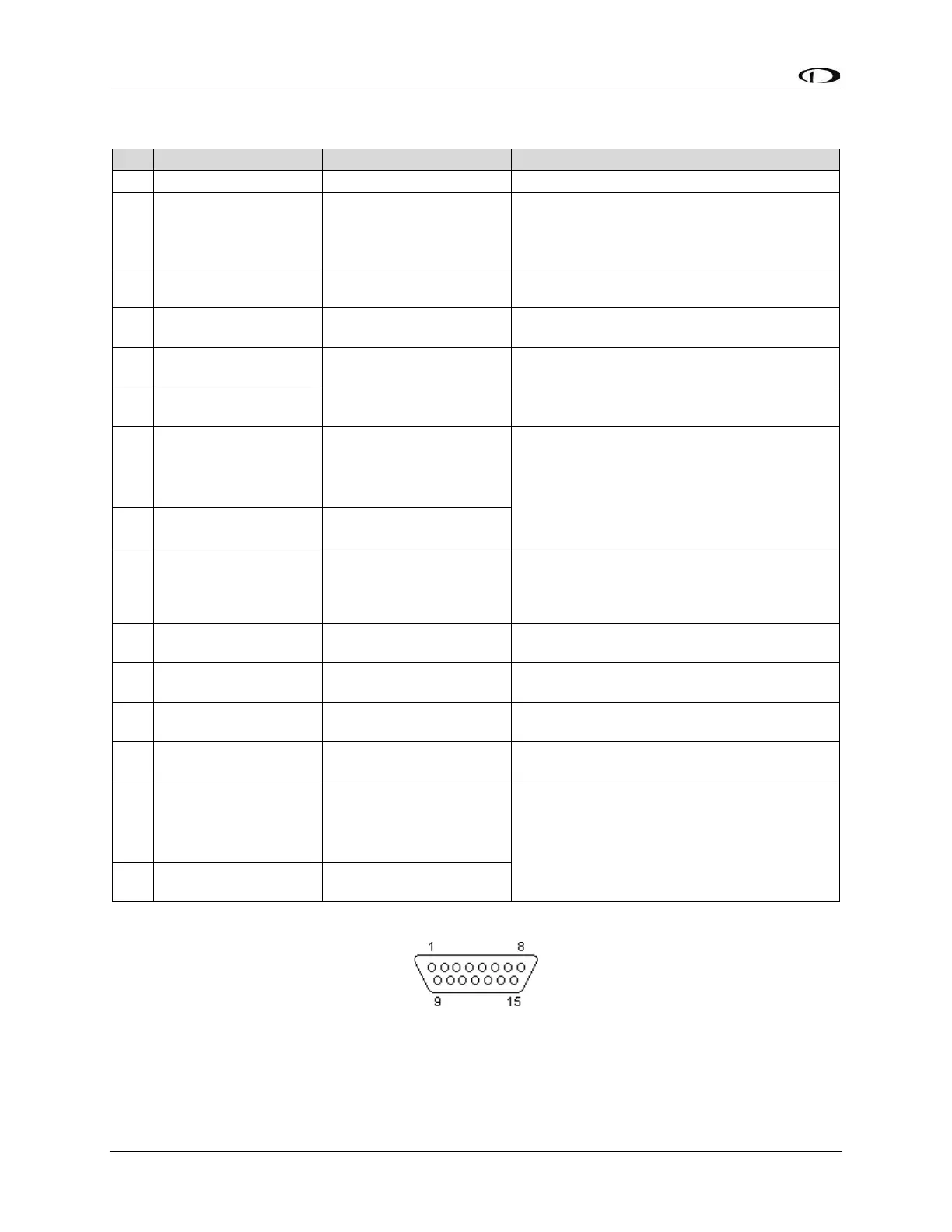
25.6.9 SV-COM-PANEL Pinout (D15M)
Figure 149: SV-COM-PANEL D15F Connector Pin Numbering
The SV-COM-PANEL-uses a D15M connector for connecting to the SV-COM-T8 COM
radio module. Figure 149 above shows the pin numbering for the mating D15F connector,
installed on the cable that plugs into this connector, from the rear (pin insertion) view.