Display Operation
21-2 SkyView HDX System Installation Manual - Revision E
21.2 Display Bezel Layout
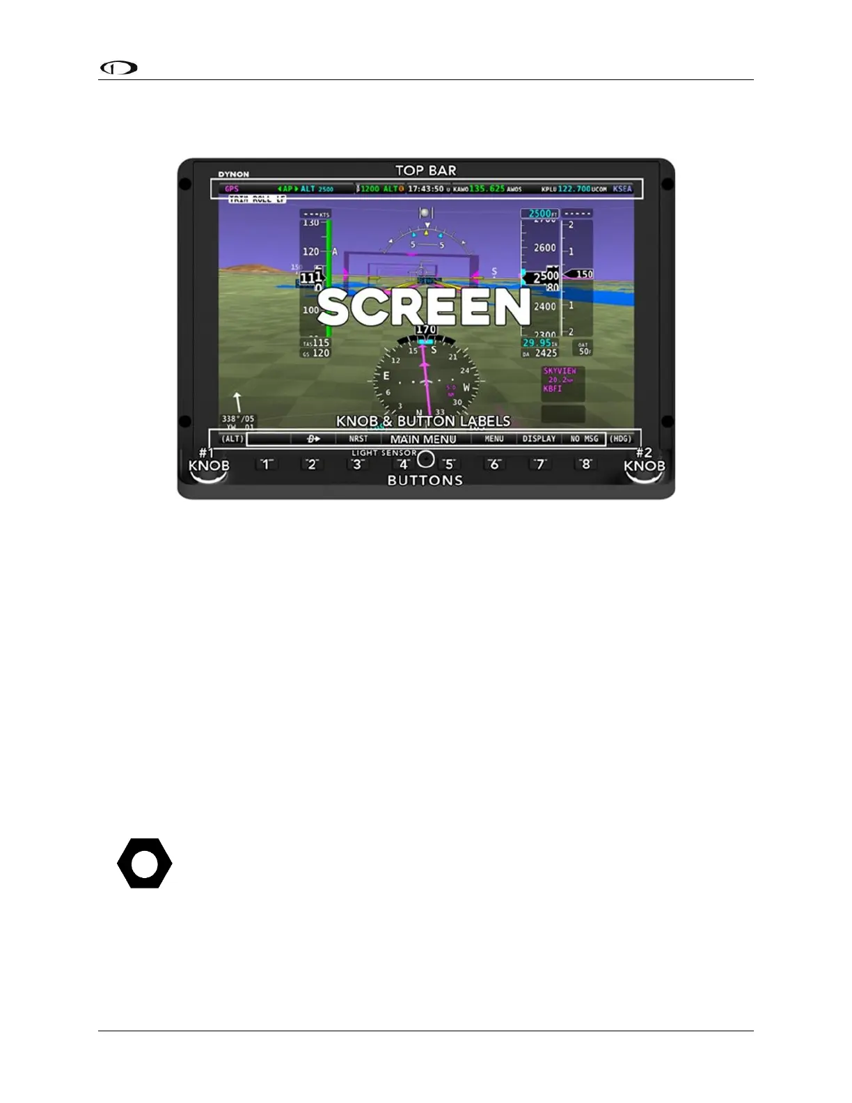
The following diagram illustrates the front of an SV-D1000 display and its important parts.
Figure 120: SkyView Display Front Bezel Layout
Note the top bar, screen, joystick and button labels, light sensor, two (2) joysticks and
eight (8) buttons.
The top bar displays important textual information. The top bar shows time, autopilot
status, and transponder status (SV-XPNDR-261 or Garmin GTX-327 only). Reference the
LOCAL DISPLAY SETUP Menu Section of this manual for details on how to configure the
top bar.
The screen shows PFD, Engine, and Moving Map data, configuration information, and
system alerts. Its layout is user-configurable. Reference the SkyView Pilot’s User Guide
for instructions on how to configure the layout of your screen.
Joystick and button labels are also on the screen. Joystick and button functionality is
contextual based on what is onscreen, and these labels show the user the current
function. For example, the (RNG) label Joystick 2 in Figure above shows that turning that
joystick will either increase or decrease the range shown on the Moving Map.
Each SkyView display has an integrated light sensor in the bezel. This light sensor can
be used for automatic backlight level management. Reference the Display Setup Section
of this manual for instructions on how to configure the display for automatic backlight level
management.