SV-ADSB-472 ADS-B IN Receiver Installation and Configuration
SkyView HDX System Installation Manual - Revision E 14-5
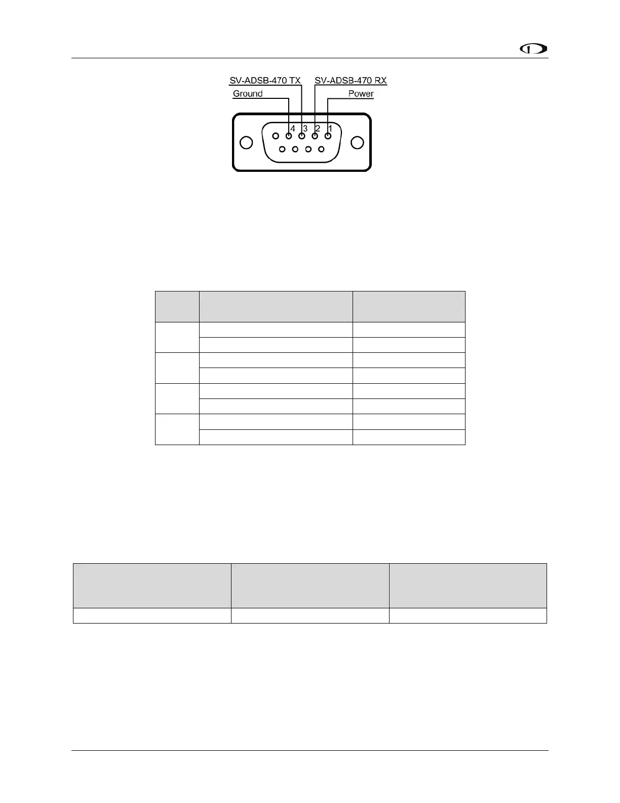
Figure 96: SV-ADSB-472 Connector Diagram
(From Rear of D9M Connector on the SV-ADSB-HARNESS)
The information in the table below shows the connections for each of SkyView’s nominally
available serial ports (serial port 5 is usually used for connection to the SV-GPS-2020
module). Only ONE (1) of the following serial ports will be used:
Table 36: Example SkyView/SV-ADSB-472 Serial Port Connections
14.2.2 Power/Ground Input
The SV-ADSB-472 can be powered by 10-30 Volts DC. 22 AWG wire is sufficient for wire
runs up to 50 feet (15.24 m) for this application. Note that the SV-ADSB-472 must be
connected to aircraft power – none of SkyView’s voltage outputs can provide a sufficient
amount of power to power the SV-ADSB-472.
Table 37: SV-XPNDR-261 Power Consumption
Approximate current
consumption at 12 volts
DC
Approximate current
consumption at 24 volts
DC
14.2.3 Serial RX/TX
All communication between the SV-ADSB-472 module and SkyView is accomplished via
a single bidirectional serial connection. To accomplish this:
• Choose an unused serial port on each display to connect the SV-ADSB-472 to.
Note that both the TX and RX sides of the serial port are needed, and both the