SV-ADSB-472 ADS-B IN Receiver Installation and Configuration
14-4 SkyView HDX System Installation Manual - Revision E
14.2 Electrical Installation
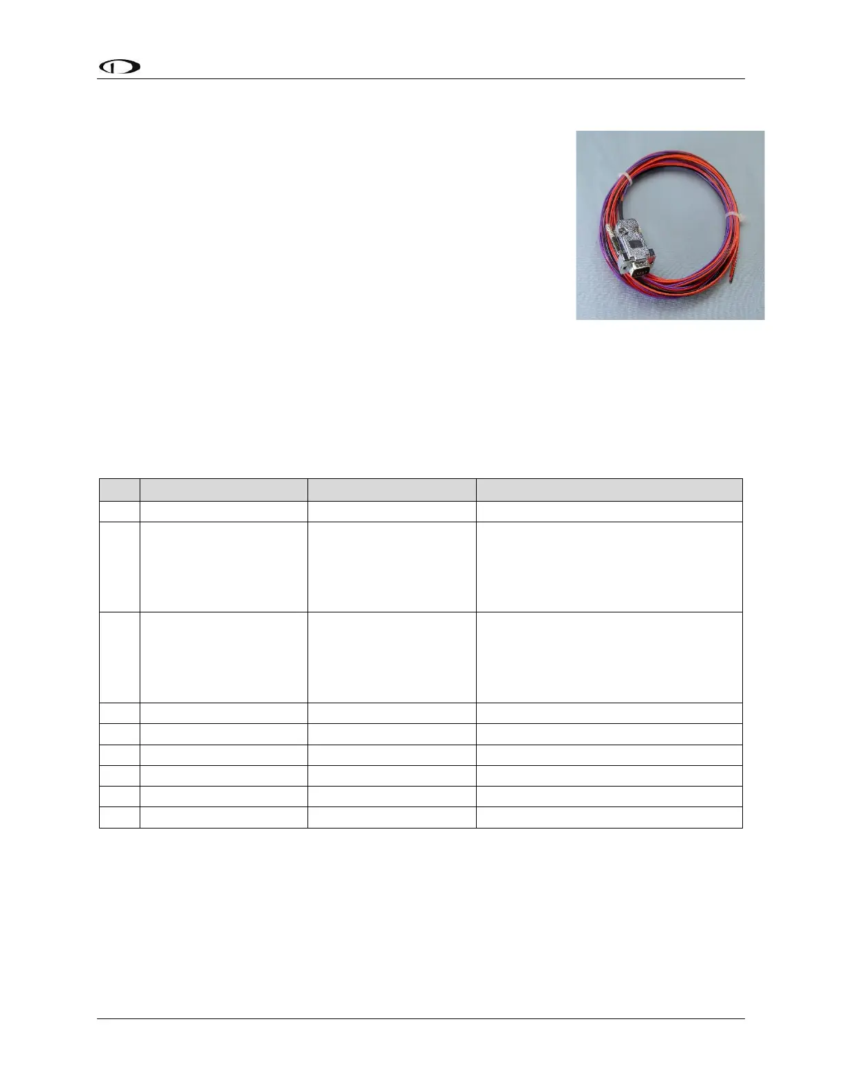
For connecting the SV-ADSB-472 to your SkyView system,
Dynon Avionics offers the optional SV-HARNESS-ADSB
harness (pictured at right). This harness is not included with the
SV-ADSB-472. It comes with 15 feet (4.572 m) of wire, and the
connector is pre-wired. If required, the harness can be
shortened, or lengthened (length is not critical). Table 35: SV-
HARNESS-ADSB (below) reflects the wiring colors of the SV-
HARNESS-ADSB.
Additional harness construction and wiring information can be
found in Section 25 Appendix C: Wiring and Electrical
Connections.
The SV-ADSB-472 has a single D9F connector which provides
the data and power inputs to the module. A single BNC connector
attaches to the antenna.
14.2.1 SV-HARNESS-ADSB – Pinout (D9F on module / D9M on harness)
Table 35: SV-HARNESS-ADSB Wiring
Data Input from SkyView Display(s):
Serial 1 – Pin 4 (Brown / Orange), or
Serial 2 – Pin 6 (Yellow / Orange), or
Serial 3 – Pin 8 (Green / Orange), or
Serial 4 – Pin 10 (Blue / Orange)
Data Output to SkyView Display(s):
Serial 1 – Pin 3 (Brown / Violet), or
Serial 2 – Pin 5 (Yellow / Violet), or
Serial 3 – Pin 7 (Green / Violet), or
Serial 4 – Pin 9 (Blue / Violet)
The pin out depicted in Figure 96 below depicts the view from the rear of your D9M
connector – the view you will have of your harness connector as you are inserting pins
into the harness. Note that the pin numbers are labelled on the face of both the female
and male connector.