Appendix C: Wiring and Electrical Connections
SkyView HDX System Installation Manual - Revision E 25-15
(determined by
installer)
(determined by
installer)
(determined by
installer)
Pins 24/25 are the same TX signal. Provided for
convenience when connecting multiple ARINC
receivers.
(determined by
installer)
Pins 24/25 are the same TX signal. Provided for
convenience when connecting multiple ARINC
receivers.
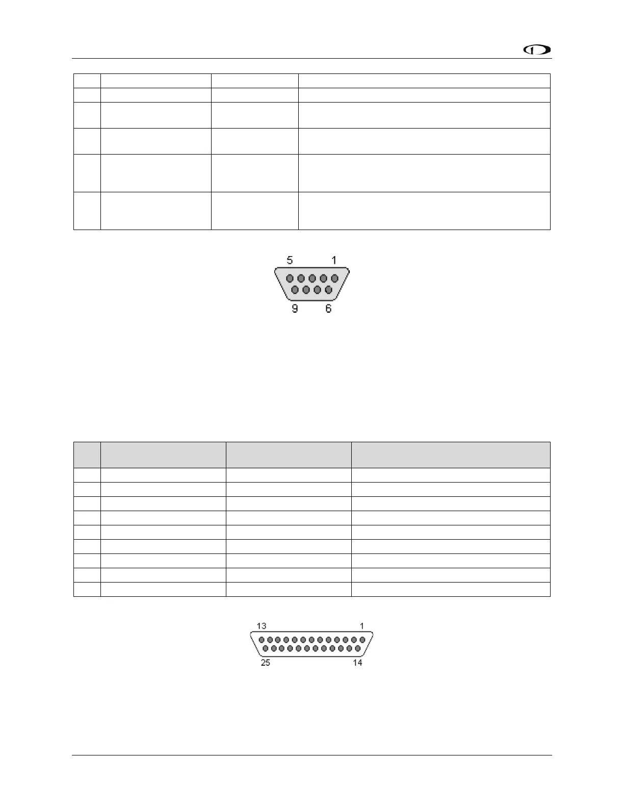
25.6.6 SV-ADSB-472 Pinout (SV-HARNESS-ADSB)
Figure 146: SV-ADSB-472 D9M Connector Pin Numbering
The SV-ADSB-472 uses a D9F connector (included with the SV-NET-ADSB harness).
Figure 146 above shows pin numbering for the mating D9M connector, installed on the
SV-HARNESS-ADSB, from the rear (pin insertion) view.
Note – this connector is NOT a SkyView Network Connector.
Table 72: SV-ADSB-472 D9F Pinout
Connect to Aircraft Power
Connect to Aircraft Ground
25.6.7 SV-XPNDR-261 Pinout (SV-HARNESS-XPNDR)
Figure 147: SV-XPNDR-261 D25M Connector Pin Numbering