SV-XPNDR-261 Transponder Installation and Configuration
12-12 SkyView HDX System Installation Manual - Revision E
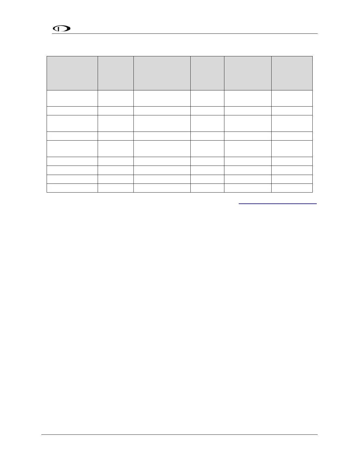
Table 31: Maximum Usable Lengths of Some Common Coaxial Cable Types
Contact Electronic Cable Specialists on +1 414 421 5300 or at http://www.ecsdirect.com
for their data sheets. Contact SSB-Electronic GmbH on +49-2371-95900 or at
http://www.ssb.de for their data sheets.
When routing the cable, ensure that you:
• Route the cable away from sources of heat.
• Route the cable away from potential interference sources such as ignition
wiring, 400Hz generators, fluorescent lighting and electric motors.
• Allow a minimum separation of one (1) foot / 12 inches (3.5 cm) from an ADF
antenna cable.
• Keep the cable run as short as possible.
• Avoid routing the cable around tight bends.
• Avoid kinking the cable even temporarily during installation.
• Secure the cable so that it cannot interfere with other systems.
12.2.11 Antenna TNC Female Connector
This section describes the technique for attaching the antenna cable to a TNC Male
connector. A TNC Male connector is not supplied with the SV-XPNDR-261. The SV-
XPNDR-261 has a TNC Female connector. Therefore, you will need to source a TNC
Male connector that is compatible with the antenna cable type that meets your aircraft’s
needs. Alternatively, especially if the transponder antenna you have purchased
incorporates coaxial cable and a “BNC” connector, you can purchase a “Male TNC to
Female BNC” adapter (see below).