EasyManua.ls Logo

Dynon SkyView HDX - SV-ARINC-429 Pinout

Dynon SkyView HDX
374 pages
Print Icon
To Next Page IconTo Next Page
To Previous Page IconTo Previous Page
Loading...
Appendix C: Wiring and Electrical Connections
25-14 SkyView HDX System Installation Manual - Revision E
SV-EMS-220 D25F
Thermocouple Connector Pin
EMS 25-pin
Thermocouple
Harness Wire Color*
Description
22
White
CHT2 WHITE
23
Yellow
EGT2 YELLOW
24
White
CHT1 WHITE
25
Yellow
EGT1 YELLOW
*Note: this is the 6-cylinder CHT/EGT harness.
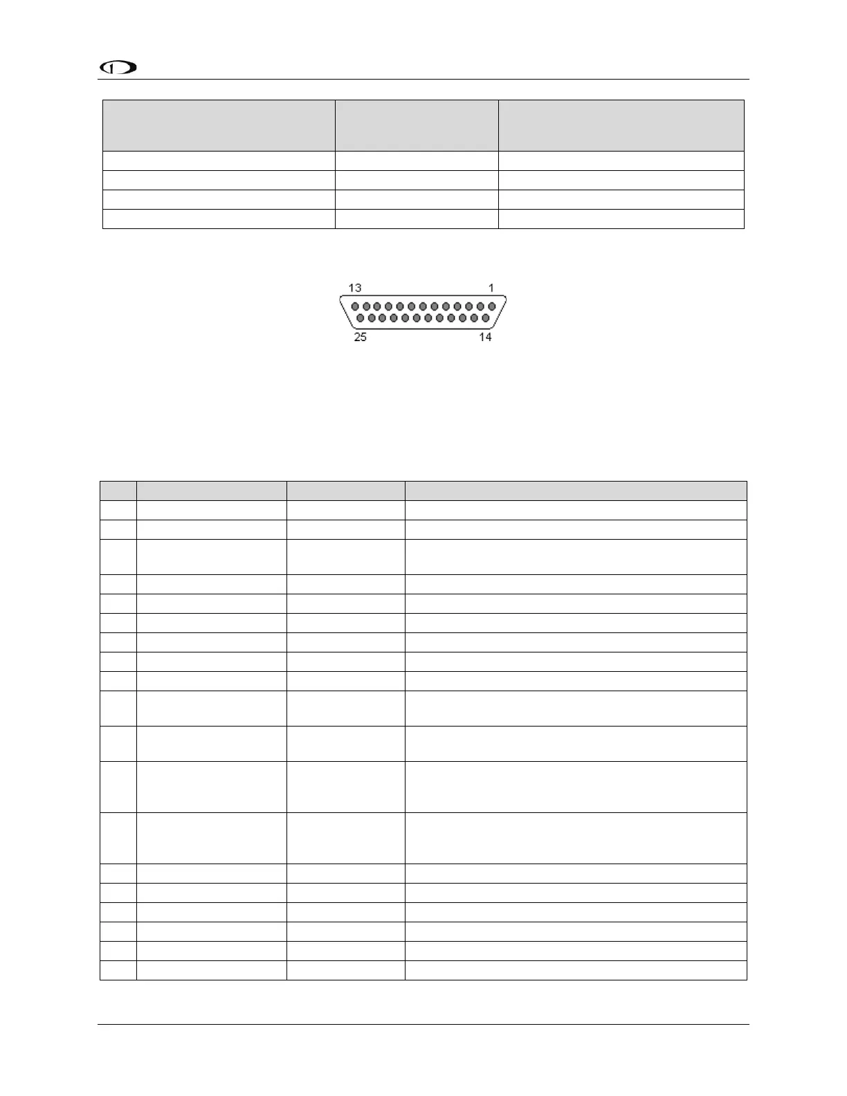
25.6.5 SV-ARINC-429 Pinout
Figure 145: SV-ARINC-429 D25M Connector Pin Numbering
The SV-ARINC-429 uses a D25F connector for connecting to ARINC-429 devices. Figure
145 above shows the pin numbering for the mating D25M connector, installed on the
cable that plugs into this connector, from the rear (pin insertion) view.
Table 71: SV-ARINC-429 D25F Connector
Pin
Wire Color
Function
Notes
1
N/A
No Connect
-
2
N/A
No Connect
-
3
(determined by
installer)
Serial RX
Aviation Format Only from
Connected ARINC-429 GPS
4
N/A
No Connect
-
5
N/A
No Connect
-
6
N/A
No Connect
-
7
N/A
No Connect
-
8
N/A
No Connect
-
9
N/A
No Connect
-
10
(determined by
installer)
ARINC 2 RX B
-
11
(determined by
installer)
ARINC 1 RX B
-
12
(determined by
installer)
ARINC TX B
Pins 12/13 are the same TX signal. Provided for
convenience when connecting multiple ARINC
receivers.
13
(determined by
installer)
ARINC TX B
Pins 12/13 are the same TX signal. Provided for
convenience when connecting multiple ARINC
receivers.
14
N/A
No Connect
-
15
N/A
No Connect
-
16
N/A
No Connect
-
17
N/A
No Connect
-
18
N/A
No Connect
-
19
N/A
No Connect
-

Table of Contents

Other manuals for Dynon SkyView HDX

Related product manuals