SV-XPNDR-261 Transponder Installation and Configuration
SkyView HDX System Installation Manual - Revision E 12-5
12.2 Electrical Installation
12.2.1 SV-XPNDR-261 Harness Construction
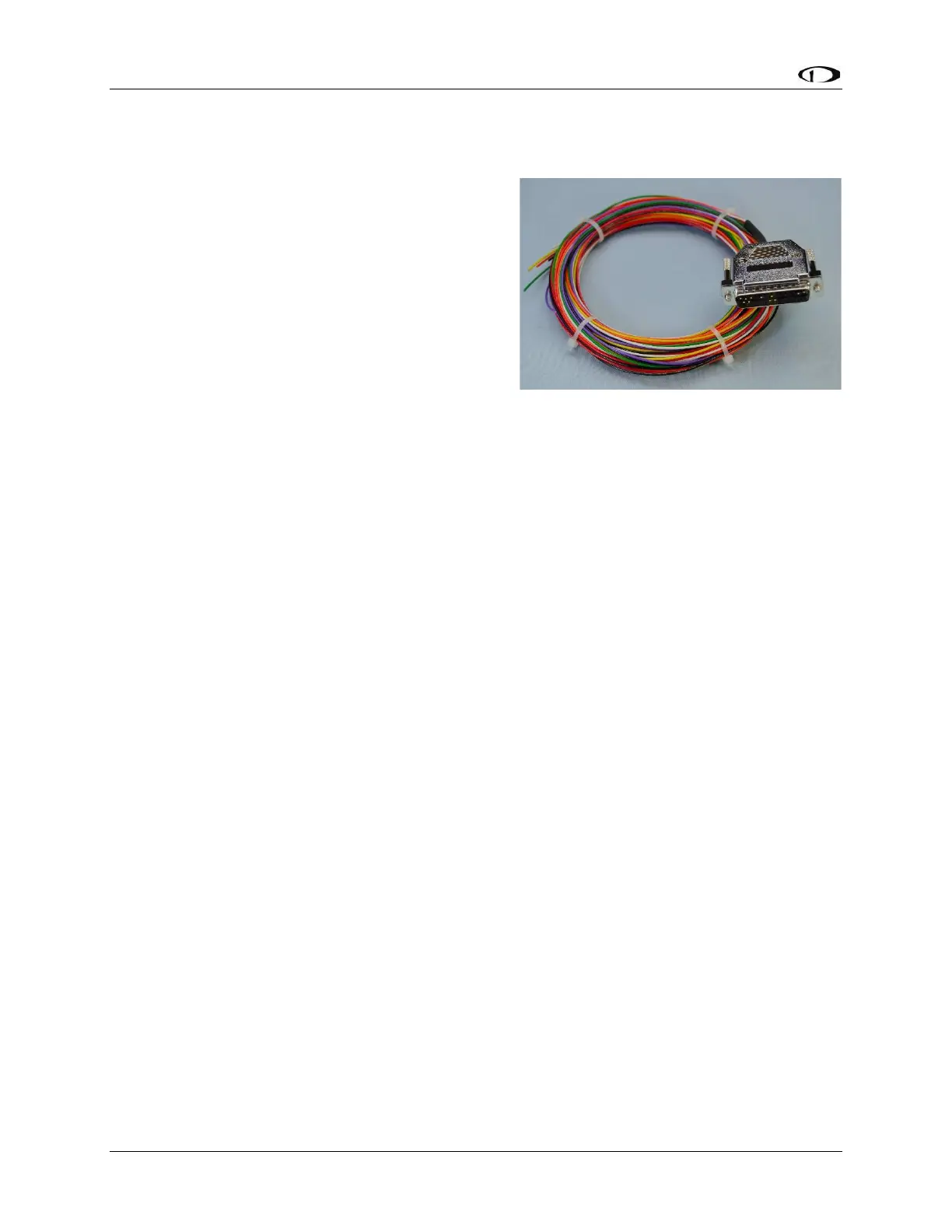
For connecting the SV-XPNDR-261, Dynon
Avionics offers the optional SV-HARNESS-
XPNDR harness (pictured at right). This harness
is not included with the SV-XPNDR-261. It
comes with 15 feet (4.572 m)of wire, and the
connector is pre-wired. If required, the harness
can be shortened, or lengthened (length is not
critical).
Table 29: SV-HARNESS-XPNDR Pinout (below)
reflects the wiring colors of the SV-HARNESS-
XPNDR.
The SV-XPNDR-261 has a single D25F connector which provides the data and power
inputs to the SV-XPNDR-261. A single TNC female coaxial connector attaches to the
antenna.
Because the SV-XPNDR-261 can be mounted in a variety of locations, the harness length
requirements will vary between various aircraft.
The SV-XPNDR-261 package includes a 25-pin connector and pins if you wish to
fabricate your own harness. Refer to the sections below for detailed wiring information.
Note that your connector kit may contain a 1.21K resistor. This resistor is only used if you
intend to connect a certified GPS receiver for ADS-B Out functionality.
Additional harness construction and wiring information can be found in Section 25
Appendix C: Wiring and Electrical Connections.