SV-BUTTON-LEVEL Autopilot Level Button Installation
18-2 SkyView HDX System Installation Manual - Revision E
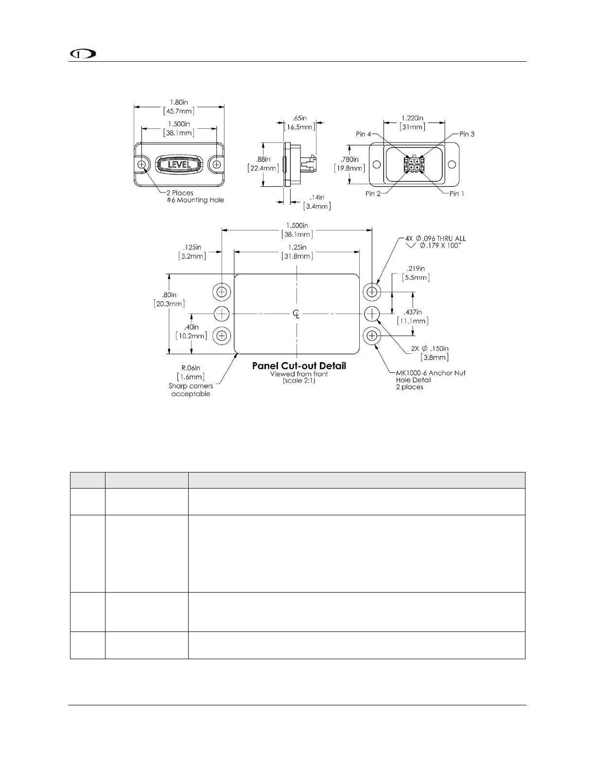
18.1 Mechanical Installation
Figure 114: SV-BUTTON-LEVEL Installation Dimensions (Not to Scale)
18.2 Electrical Installation
Table 43: Connections for SV-BUTTON-LEVEL
Connection Points / Notes
Aircraft Power; connect to same point as SkyView display Power
(Red) wires, Pins 1 and 20.
SkyView Pin 26 – White wire
24V electrical systems require a 1.1KΩ resistor (included in the kit)
in series with the SV-BUTTON-LEVEL’s white wire and the SkyView
display’s Pin 26 white wire.
If you have multiple SkyView displays, connect this wire to only one
(1) display.
SkyView Pin 28 – Orange / Black Connect wire. If you have multiple
SkyView displays, see the note below – Considerations for SV-
BUTTON-LEVEL.
Aircraft Ground; connect to the same point as SkyView display
Ground (Black) wires, Pins 21 and 22.