Appendix C: Wiring and Electrical Connections
25-18 SkyView HDX System Installation Manual - Revision E
Table 75: SV-COM-PANEL D15M Connector
(determined by
installer)
From 10-30V DC @ 5A (SV-COM-T8)
(determined by
installer)
(determined by
installer)
Optional – for Grounding Pin 7 (Flip/Flop Switch).
Switch may also be grounded locally.
(determined by
installer)
(determined by
installer)
(determined by
installer)
(determined by
installer)
External
Flip/Flop Switch
(optional)
Push Button Normally Open to Ground (Pin 3 or
Local Ground)
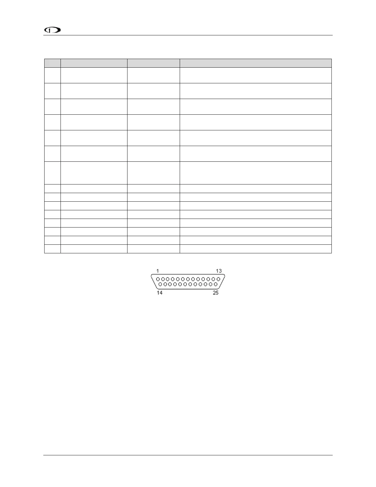
25.6.10 SV-COM-T8 Pinout
Figure 150: SV-COM-T8 D25F Connector Pin Numbering
The SV-COM-T8 uses a D25M connector for connecting to the SV-COM-PANEL. Figure
150 above shows the pin numbering for the mating D25F connector, installed on the cable
that plugs into this connector, from the rear (pin insertion) view.