SV-EMS-220 Engine Monitoring System Installation and Configuration
SkyView HDX System Installation Manual - Revision E 10-17
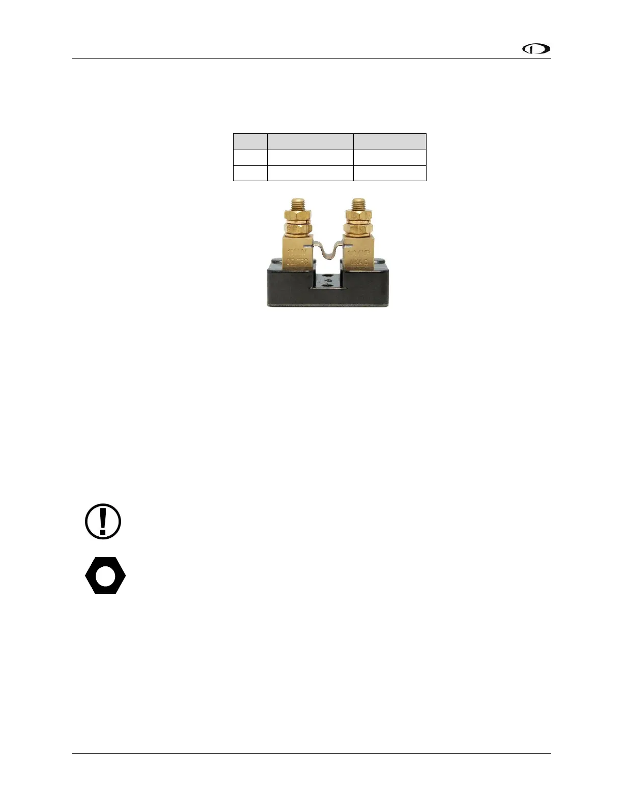
10.2.16 Ammeter Shunt
Table 18: AMPS SHUNT Pins
The ammeter shunt should be mounted so that the metal part of the shunt cannot touch
any part of the aircraft. The ammeter shunt can be installed in your electrical system in
one (1) of three (3) locations as shown in the figure below.
• Position A – Ammeter indicates current flow into or out of your battery. In this
position, it will show both positive and negative currents (i.e., -60 amps to +60
amps).
• Position B–Ammeter indicates only the positive currents flowing from the
alternator to both the battery and aircraft loads. (0A-60A).
• Position C–Ammeter indicates the current flowing only into the aircraft loads.
(0A-60A).
Note that the ammeter shunt is not designed for the high current required by
the starter and must not be installed in the electrical path between the battery
and starter.
The Ammeter Shunt packaging may be marked 40mV/40A. However, Dynon
Avionics rates the shunt for up to 60A loads.