EFIS-D10A Standby Display Installation and Configuration
20-2 SkyView HDX System Installation Manual - Revision E
Table 46: Pin Assignments for Power Inputs
Provides primary power to the instrument. The EFIS-
D10A will switch on upon application of power.
Connect to a switched power source. Will not be
adversely affected by engine cranking.
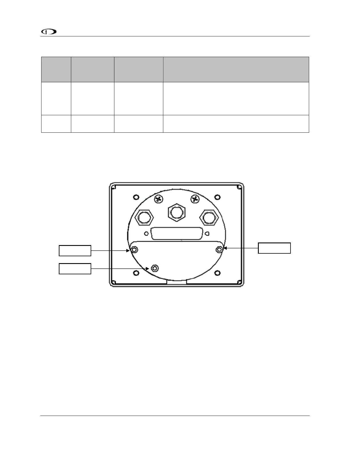
20.6 EFIS-D10A Battery Installation
1. Remove the three 7/64” hex screws from the battery door of the Dynon EFIS-
D10A. Do not remove the Phillips or D-sub screws.
Figure 117: D10A Battery Pack Installation
2. Insert the battery with the “bumpy” side up, toward the foam.
3. Connect the battery connector to the battery. The connector is keyed; make sure
it is positioned correctly.
4. Position the connector so it is centered on the end of the pack. Verify battery pack
is properly centered, not under screw 2.
5. Reinsert screw 2 first and tighten to 12 in-lbs.
6. Caution: Screws 1 and 3 are screwed into the extrusion and are easy to over-
torque. Press on the back plate as you insert screws 1 and 3 and tighten 4.5 in-lbs
(72 in- ounces).