Appendix C: Wiring and Electrical Connections
SkyView HDX System Installation Manual - Revision E 25-5
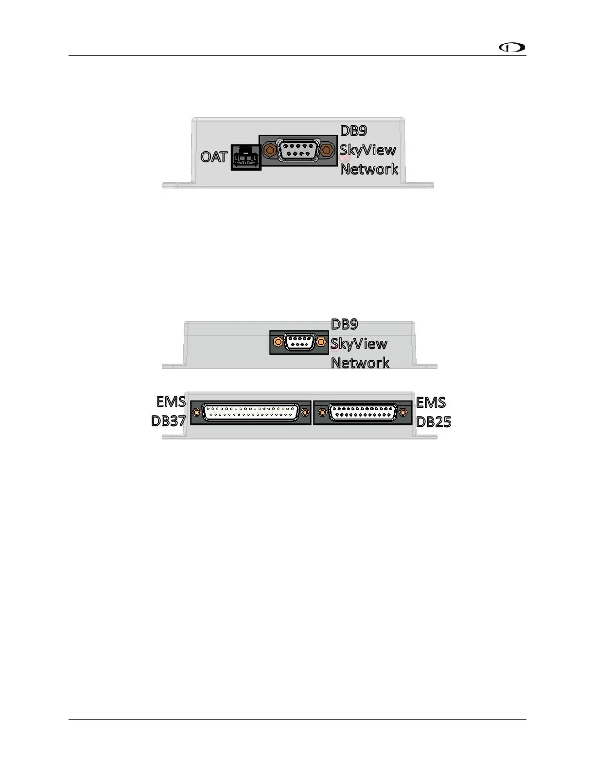
• One (1) D9M SkyView network connector.
• One (1) 2-pin OAT sensor connector (only compatible with the SV-OAT-340).
Figure 137: SV-ADAHRS-200/201 Connectors
The SkyView EMS Module (SV-EMS-220) has three (3) connectors as illustrated in Figure
138:
• One (1) D9M SkyView network connector.
• One (1) D37M for various transducer connections.
• One (1) D25F for thermocouple connections.
Figure 138: SV-EMS-220 Connectors
The SV-GPS-2020 receivers include four (4) unterminated wires. These wires may be
trimmed or spliced and extended as needed to suit the installation location. Match the
colors of these wires with the corresponding colors on the display harness as mentioned
in the Electrical Installation Section of SV-GPS-2020 GPS Antenna/Receiver Installation.
The SV-BAT-320 has one (1) connector. Do not add more wire into the SV-BAT-320 wire
bundle.
Each SkyView servo has seven (7) unterminated wires. Reference Section 16: AP Servo
Installation and Configuration for more information.
25.6 SkyView Equipment Electrical Connector Pinout Tables
See tables on the follow pages for connector pin function descriptions. Tables for the USB
jacks, RJ45 jack, OAT connector, and battery connector are not included.