SV-EMS-220 Engine Monitoring System Installation and Configuration
10-10 SkyView HDX System Installation Manual - Revision E
Note that you may need access to the SV-EMS-220’s +5 Volts auxiliary supply for other
sensor installations, so make allowances for breaking out the connection to other areas.
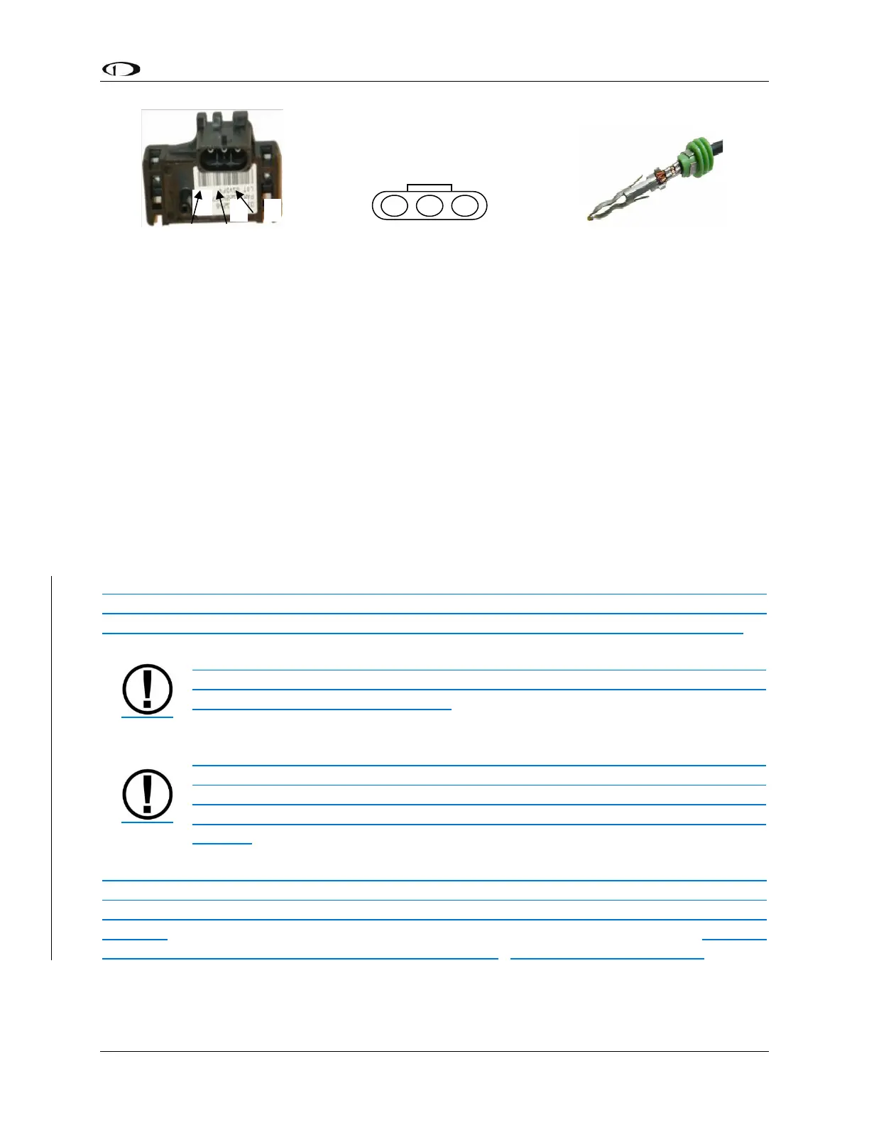
Route the three (3) wires to the location where you would like to mount the manifold
pressure sensor.
Plug the crimped pins into the included Weatherpack connector. Now, mount the manifold
pressure sensor in a secure fashion using the mounting holes on either side of the sensor.
The pressure port on the manifold pressure sensor requires 1/4” (6.35 mm) inner diameter
tubing for a secure fit. You may need to use adapters to convert down to smaller inner
diameter tubing for your specific engine. We recommend that you use pipe clamps at
every transition point, including at the sensor itself.
10.2.11 Oil Pressure Sensor
Mount the oil pressure sensor securely to the airplane's structure using appropriate
AN/MS hardware fittings, clamps, and flexible hose. Do not mount the sensor directly to
the engine's pressure port. The pressure sensor has a 1/8-27 NPT pipe thread fitting.
DO NOT mount sensor directly to engine or other areas of high vibration.
Always mount the sensor to the airframe structure, and connect it with flexible
hose to minimize vibration effects. Avoid damaging plastic portion of sensor
when threading it into matching fitting.
Always use an AN/MS fitting with a restriction intended for pressure indication
systems when connecting sensors to a pressure port on an engine. Restrictor
holes minimize leakage in the event of a failure of any of the items
downstream of the pressure port connection, allowing time for an emergency
landing.
As of 2020, Dynon Avionics no longer supplies the original 0-150 PSI Kavlico sensor (P/N
503388-000). For new installations, use the new 150 PSI Kavlico sensor (P/N 503851-
000). The new sensor is a direct mechanical and electrical replacement for the original
sensor. Installation methods (see above) are the same for both sensors. Updated
software sensor definitions are available from Dynon's software download page.
Figure 49: Connection
diagram for sensor with all
black wires only
Figure 50: Pin insertion (rear)
view of supplied connector.
Figure 51: Detail view of
properly crimped pin.