SV-XPNDR-261 Transponder Installation and Configuration
SkyView HDX System Installation Manual - Revision E 12-29
when the aircraft is on the ground should leave the SV-XPNDR-261 in GND
mode; when the aircraft becomes airborne, the mode should switch
automatically to ALT.
• Interrogations to verify the receiver sensitivity. A Mode S transponder should
have a minimum triggering level (MTL) of between -77 dBm and -71 dBm.
Failure to meet this requirement usually indicates antenna or coaxial cable
problems.
• Interrogations to verify the transmitted power. A Class 1 installation should
have no less than 125 Watts at the antenna (and no more than 500 Watts). A
Class 2 installation should have no less than 71 Watts at the antenna (and no
more than 500 Watts). Failure to meet this requirement is also generally due to
antenna or wiring issues.
• Where installed, verification of the GPS position source and ADS-B outputs.
Whenever a valid position is received by the transponder and the transponder
is in any mode other than Standby, ADS-B Extended Squitter should be
observed on the transponder test set.
• Ensure all regulatory requirements are met. In the United States, the
transponder must be tested and inspected per FAR 91.413.
12.7 Transponder Warnings (Transponder Self Diagnostics)
The SV-XPNDR-261 includes limited self-diagnostic capability. If a SV-XPNDR-261 fault
is detected, a system message will be displayed: XPNDR WARNING MESSAGE. To see
the detailed information on the fault, go to SETUP MENU > TRANSPONDER SETUP.
The words TRANSPONDER WARNING will be displayed in Yellow; right-click the knob
and see the specific warning. The table below provides a recommendation for each
specific warning.
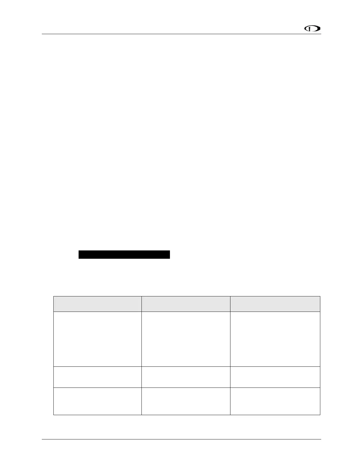
Table 33 – SV-XPNDR-261 Self Diagnostic Messages
Generally, this is an installation
issue with antenna, feedline, or
the connector. Check the
antenna, feedline, or connector.
A visual inspection is often not
sufficient to find the fault with
the antenna, feedline, or
connector.