EasyManua.ls Logo

Dynon SkyView HDX - Page 182

Dynon SkyView HDX
374 pages
Print Icon
To Next Page IconTo Next Page
To Previous Page IconTo Previous Page
Loading...
SV-XPNDR-261 Transponder Installation and Configuration
12-6 SkyView HDX System Installation Manual - Revision E
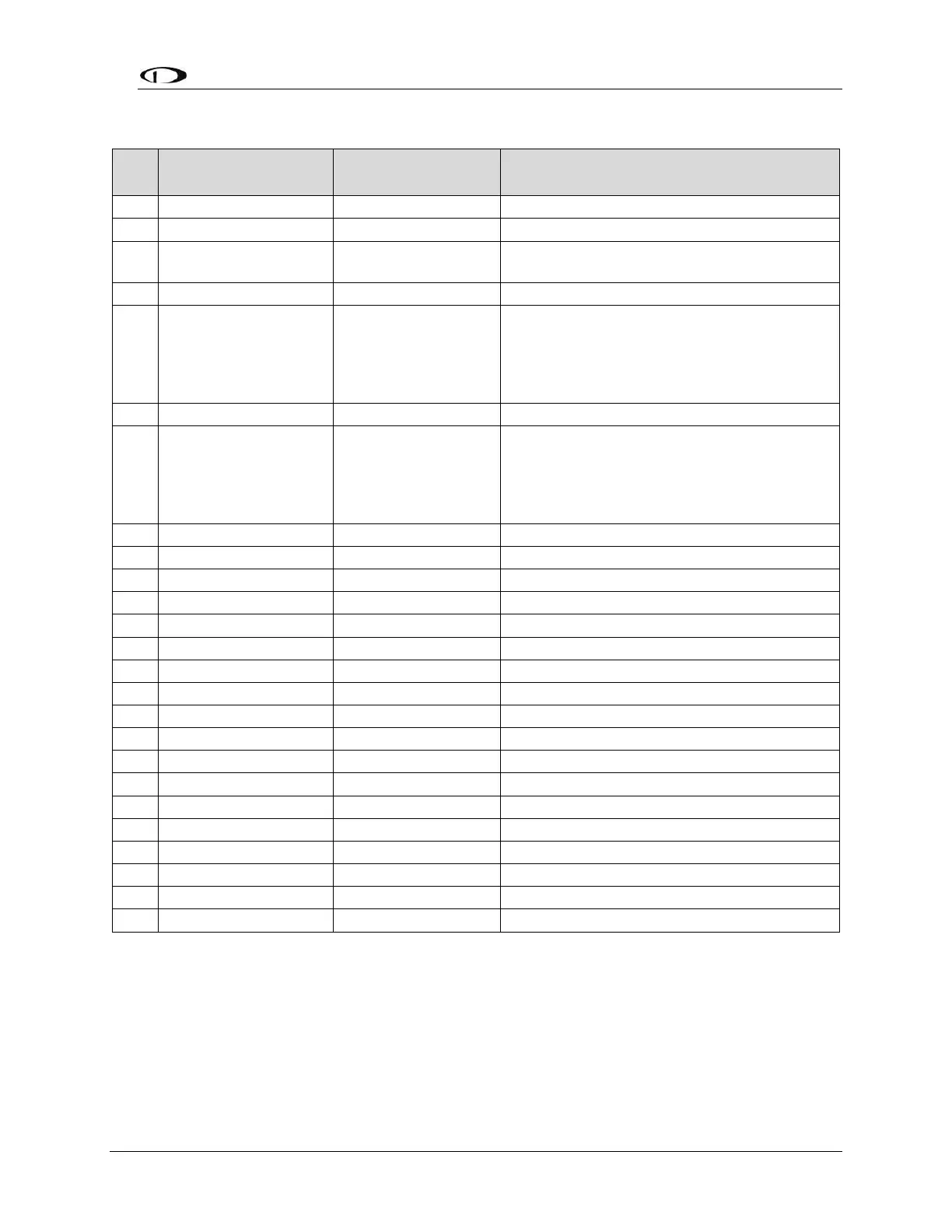
Table 29: SV-HARNESS-XPNDR Pinout
Pin
Function
SV-HARNESS-
XPNDR Color
Notes
1
Loopback 1
White
Connect to Pin 2
2
Loopback 1
White
Connect to Pin 1
3
GPS Serial Input
White
Certified GPS Only for ADS-B Out (see
explanation below)
4
No Connection
No wire installed
-
5
SV-XPNDR-261
Serial RX
Orange
Data Input from SkyView Display(s):
Serial 1 Pin 4 (Brown / Orange), or
Serial 2 Pin 6 (Yellow / Orange), or
Serial 3 Pin 8 (Green / Orange), or
Serial 4 Pin 10 (Blue / Orange)
6
No Connection
No wire installed
-
7
SV-XPNDR-261
Serial TX
Violet
Data Output to SkyView Display(s):
Serial 1 Pin 3 (Brown / Violet), or
Serial 2 Pin 5 (Yellow / Violet), or
Serial 3 Pin 7 (Green / Violet), or
Serial 4 Pin 9 (Blue / Violet)
8
No Connection
No wire installed
-
9
No Connection
No wire installed
-
10
No Connection
No wire installed
-
11
No Connection
No wire installed
-
12
Loopback 2
White
Connect to Pin 13
13
Loopback 2
White
Connect to Pin 12
14
Ground
Black
Connect to Aircraft Ground
15
11-33V DC
Red
Connect to Aircraft Power
16
No Connection
No wire installed
-
17
External Standby In
No wire installed
Optional: Not Commonly Connected
18
Mutual Suppression
No wire installed
Optional: Not Commonly Connected
19
Squat Switch In
Yellow
Optional: Not Commonly Connected
20
Ident Switch In
Green
Optional: Not Commonly Connected
21
No Connection
No wire installed
-
22
No Connection
No wire installed
-
23
No Connection
No wire installed
-
24
No Connection
No wire installed
-
25
No Connection
No wire installed
-

Table of Contents

Other manuals for Dynon SkyView HDX

Related product manuals