SV-XPNDR-261 Transponder Installation and Configuration
SkyView HDX System Installation Manual - Revision E 12-7
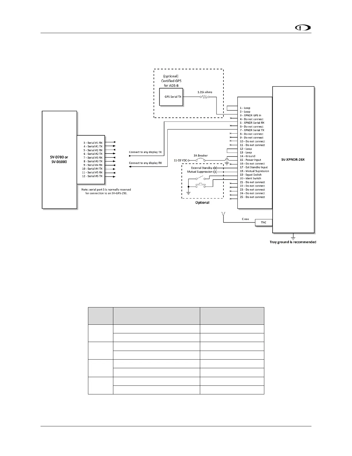
The figure below depicts how the SV-XPNDR-261 connects with other SkyView and
aircraft components. Note that many of the connections shown are optional and are not
be used in most installations.
Figure 75: SV-XPNDR-261 Wiring Diagram
The table below shows the connections for each of SkyView’s nominally available serial
ports. Serial Port 5 is usually used for connection to the SV-GPS-2020 GPS receiver.
Only ONE (1) of the following serial ports will be used to connect the SV-XPNDR-261.
Table 30: Example SkyView/SV-XPNDR-261 Serial Port Connections