EasyManua.ls Logo

Dynon SkyView HDX - Page 331

Dynon SkyView HDX
374 pages
Print Icon
To Next Page IconTo Next Page
To Previous Page IconTo Previous Page
Loading...
Appendix C: Wiring and Electrical Connections
SkyView HDX System Installation Manual - Revision E 25-13
SV-EMS-221 D37
Pin
EMS 37-pin Harness Wire
Color
Sensor (with Dynon Avionics part
number if applicable)
29
Yellow/Green
Optional External Alarm Indicator
30
Black
Signal Ground
31
White/Orange
Enhanced General Purpose Input 13
32
White/Green
Standard RPM Left Input
33
White/Blue
Standard RPM Right Input
34
Blue
Low Voltage RPM Left Input
35
Green
Low Voltage RPM Right Input
36
Blue or Unwired
CAN High from 912 iS ECU
37
Green or Unwired
CAN Low CAN High from 912 iS ECU
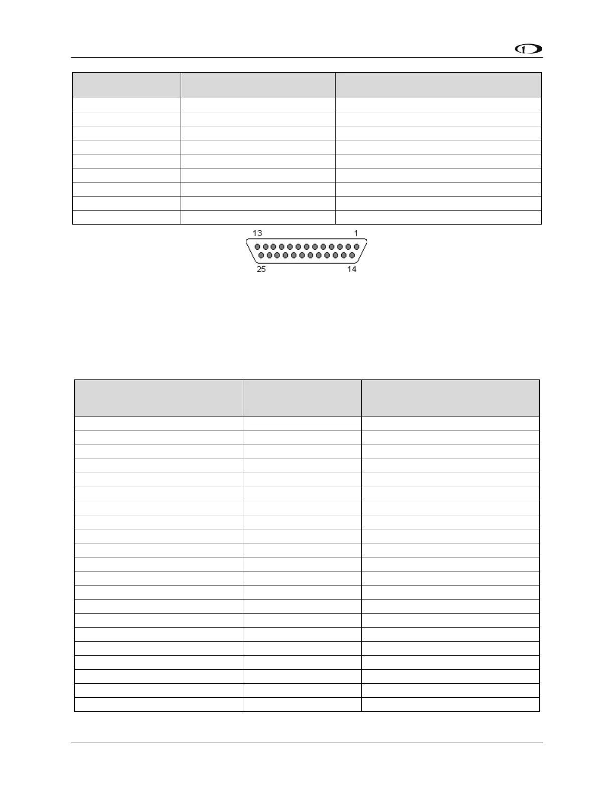
Figure 144: SV-EMS-220 D25M Connector Pin Numbering
The SV-EMS-220 uses a D25F connector for connecting most CHT/EGT (thermocouple)
sensors. Figure 144 above shows the pin numbering for the mating D25M connector,
installed on the cable that plugs into this connector, from the rear (pin insertion) view.
Table 70: SV-EMS-220 D25F Thermocouple Connector
SV-EMS-220 D25F
Thermocouple Connector Pin
EMS 25-pin
Thermocouple
Harness Wire Color*
Description
1
Do Not Connect
Do Not Connect
2
Red
CHT6 RED
3
Red
EGT6 RED
4
Red
CHT5 RED
5
Red
EGT5 RED
6
Red
CHT4 RED
7
Red
EGT4 RED
8
Red
CHT3 RED
9
Red
EGT3 RED
10
Red
CHT2 RED
11
Red
EGT2 RED
12
Red
CHT1 RED
13
Red
EGT1 RED
14
White
CHT6 WHITE
15
Yellow
EGT6 YELLOW
16
White
CHT5 WHITE
17
Yellow
EGT5 YELLOW
18
White
CHT4 WHITE
19
Yellow
EGT4 YELLOW
20
White
CHT3 WHITE
21
Yellow
EGT3 YELLOW

Table of Contents

Other manuals for Dynon SkyView HDX

Related product manuals